This helps you quickly interpret patents by identifying the three key elements:
Problems solved by technology
Method used
Benefits of technology
Benefits of technology
[0014]According to the present invention, it can be compatible in improvement in a speed by the BL capacitor reducible in the DRAM mode, and BL capacitor securing in the FRAM mode, by providing the load capacitor adjustment cell on the BL, and separately setting the capacitor on the BL between the DRAM mode and the FRAM mode.
[0015]According to the ferroelectric memory device of the present invention, it can be made to operate by the DRAM operational mode with small capacitor load for high speed operation at the time of the normal operation, and can be made to operate by the FRAM operational mode for the data hold of the power OFF period at the time of power ON / OFF.
[0016]According to the ferroelectric memory device of the present invention, improvement in the speed of operating speed of the same grade as the SRAM can achieve.
[0017]Also, according to the ferroelectric memory device of the present invention, improvement in the speed of the data restoring process at the time of the power supply cutoff can be achieved.
[0018]Moreover, according to the ferroelectric memory device of the present invention, the characteristic degradation of the ferroelectric device by the number of times reduction of polarization inversion can be suppressed.
Problems solved by technology
On the other hand, since it is necessary to drive comparatively large capacitor for control of the hysteresis characteristic of the ferroelectric capacitor, it is difficult to achieve a high speed operation of a Static Random Access Memory (SRAM) level having access time for about several ns for example, in the present condition.
Moreover, since the characteristics of the ferroelectric capacitor deteriorated gradually whenever it repeated a polarization inversion, there was a problem that the number of times of data rewriting is limited to about 1014 times per one capacitor.
Since the BL capacitor can be applied small by the trade-off only in the range in which the FRAM mode can operate, the improvement in the speed has limitations.
Method used
Image
Click on the blue label to locate the original text in one second.
Reading with bidirectional positioning of images and text.
Examples
first embodiment
Ferroelectric Memory Device
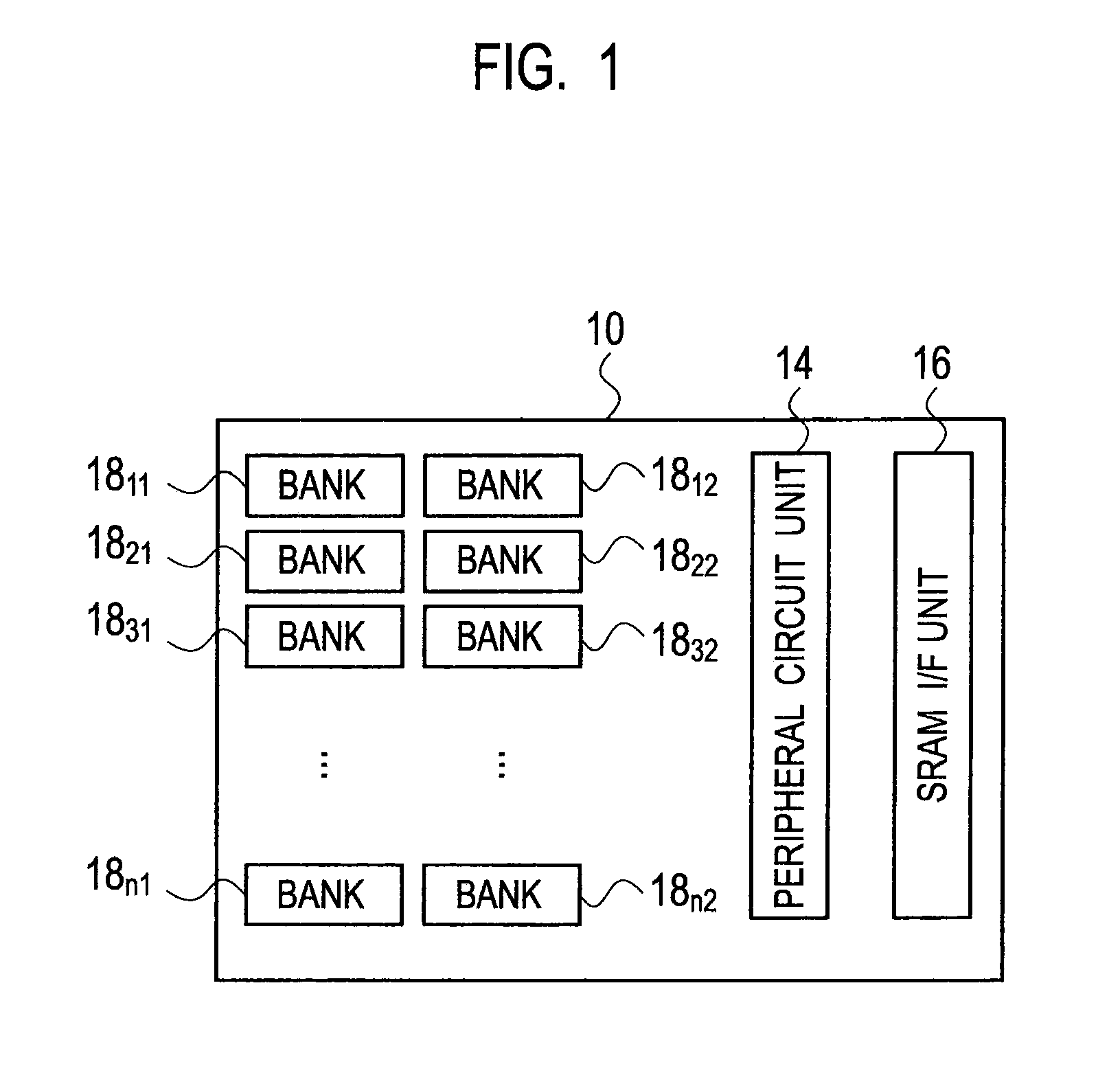
[0084]As shown in FIG. 1, a ferroelectric memory device 10 according to a first embodiment of the present invention includes: a plurality of banks 1811, 1812, . . . , 18n1, and 18n2, a peripheral circuit unit 14, and an SRAM interface (I / F) unit 16. The SRAM I / F unit 16 provides an interface compatible with SRAM for external, when connecting the plurality of banks 1811, 1812, . . . , 18n1, and 18n2 with the external.
[0085]The peripheral circuit unit 14 shows other components except the SRAM I / F unit 16 and the plurality of banks 1811, 1812, . . . , 18n1, and 18n2. The plurality of memory banks 1811, 1812, . . . , 18n1, and 18n2 compose independent ferroelectric memories, respectively, and perform write-in, read-out, and holding of data in each bank unit.
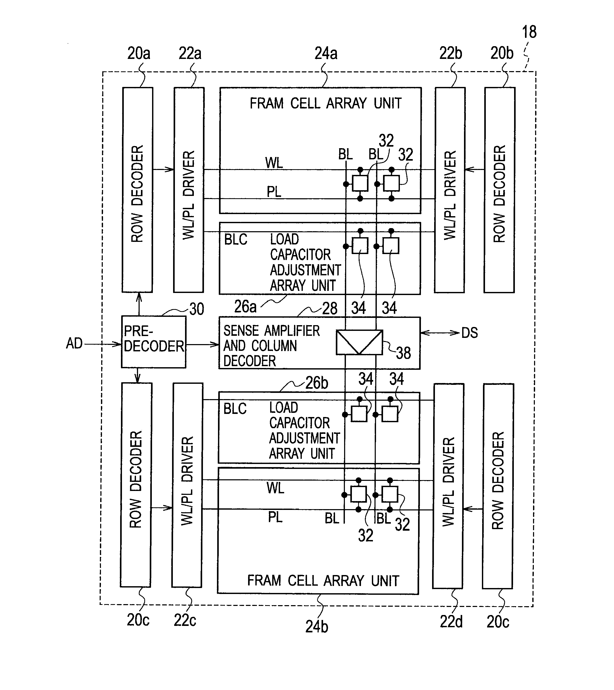
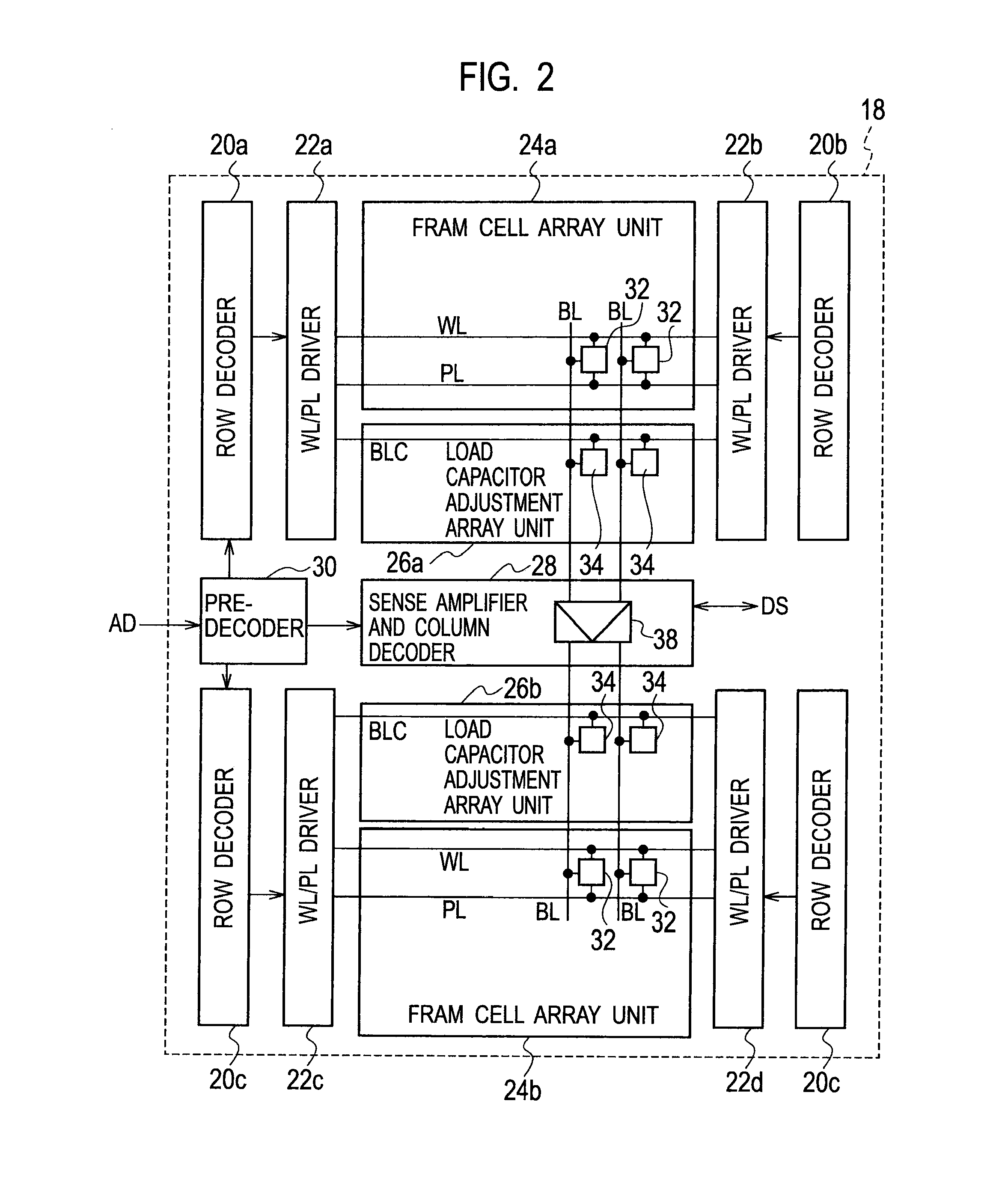
[0086]For example, as shown in FIG. 2, one bank 18 of the ferroelectric memory device 10 according to the first embodiment includes: FRAM cell array units 24a, 24b; load capacitor adjustment array units 26a, 26b disposed to be adjoining in the column direction for the FRAM cell array units 24a, 24b, respectively; a sense amplifier and column decoder 28 disposed in common to be adjoining in the column direction for the load capacitor adjustment array units 26a, 26b; word line / plate line (WL / PL) drivers 22a, 22b, and 22c, 22d disposed to be adjoining in the row direction for the FRAM cell array units 24a, 24b; row decoders 20a, 20b, and 20c, 20d disposed to be adjoining in the column direction for the word line / plate line (WL / PL) drivers 22a, 22b, and 22c, 22d, respectively; and a pre-decoder 30 which is disposed to be adjoining in the row decoders 20a, 20c and the sense amplifier and column decoder 28, and receives an address signal AD. The sense amplifier and column decoder 2...
[0101]For example, as shown in FIG. 2, another detailed schematic block configuration example of one bank 18 of the ferroelectric memory device 10 according to the present embodiment includes: FRAM cell array units 25a, 25b; a common sense amplifier and column decoder 28 disposed to be adjoining in the column direction for the FRAM cell array units 25a, 25b; WL / PL drivers 22a, 22b disposed to be adjoining in the row direction for the FRAM cell array unit 25a; WL / PL drivers 22c, 22d disposed to be adjoining in the row direction for the FRAM cell array unit 25b; row decoders 20a, 20b disposed to be adjoining in the column direction for the WL / PL drivers 22a, 22b; and row decoders 20c, 20d disposed to be adjoining in the column direction for the WL / PL drivers 22c, 22d. The bank 18 further includes a pre-decoder 30a which is disposed to be adjoining in the row decoders 20a, 20c and the sense amplifier and column decoder 28, and receives an address signal AD. The bank 18 further i...
PUM
Abstract
By separately setting a capacitor on BL depending on whether the mode is a DRAM mode or an FRAM mode, it is compatible with improvement in a speed by BL capacitor reduction in the DRAM mode and a sufficient BL capacitance in the FRAM mode.A ferroelectric memory device includes: a plurality of bit lines BL disposed in a column direction; a plurality of word lines WL disposed in a row direction; a plurality of plate lines PL and a bit linecapacitorcontrol signal BLC; a ferroelectric memory cell (32) disposed at an intersection of the plurality of bit lines BL, the plurality of word lines WL, and the plurality of plate lines PL, and composed of a ferroelectric capacitor CF and a memory celltransistor QM; and a load capacitor adjustment cell (34) disposed at an intersection of the plurality of bit lines BL and the bit line capacitor control signal BLC, and composed of a load capacitor CL and a load capacitor adjustment transistor QL.
Description
TECHNICAL FIELD[0001]The present invention relates to a ferroelectric memory device, in particular relates to a ferroelectric memory device which adjusts a capacitor of a bit line to which a memory cell is connected.BACKGROUND ART[0002]A Ferroelectric Random Access Memory (FRAM (registered trademark)) has achieved nonvolatile storage characteristics of stored data (for example, holding performance for about ten years), and excellent characteristics of a high speed data write-in performance for about several 10 ns for example, by using hysteresis characteristic which a ferroelectric capacitor has.[0003]On the other hand, since it is necessary to drive comparatively large capacitor for control of the hysteresis characteristic of the ferroelectric capacitor, it is difficult to achieve a high speed operation of a Static Random Access Memory (SRAM) level having access time for about several ns for example, in the present condition. Moreover, since the characteristics of the ferroelectric...
Claims
Application Information
Patent Timeline
Application Date:The date an application was filed.
Publication Date:The date a patent or application was officially published.
First Publication Date:The earliest publication date of a patent with the same application number.
Issue Date:Publication date of the patent grant document.
PCT Entry Date:The Entry date of PCT National Phase.
Estimated Expiry Date:The statutory expiry date of a patent right according to the Patent Law, and it is the longest term of protection that the patent right can achieve without the termination of the patent right due to other reasons(Term extension factor has been taken into account ).
Invalid Date:Actual expiry date is based on effective date or publication date of legal transaction data of invalid patent.

