Swivel tweeter mechanism for a constant phase coaxial acoustic transducer

a constant phase coaxial and tweeter technology, applied in the direction of transducer details, electrical transducers, electrical apparatus, etc., can solve the problems of affecting the sound fidelity of speakers, affecting the sound quality of speakers, etc., to achieve the effect of reducing the movement of perceivable air, and reducing the movement of air

Active Publication Date: 2010-12-23
DEFINITIVE TECH
View PDF10 Cites 9 Cited by
  • Summary
  • Abstract
  • Description
  • Claims
  • Application Information

AI Technical Summary

Benefits of technology

[0017]In another exemplary embodiment, a mechanism is disclosed to allow limited axial range of motion to prevent over twisting of wire leads connected to the tweeter. Disclosed embodiment uses a ring / stop configuration allowing two elements to each have a range of motion greater than zero degrees, but less than 360 degrees. In sum, the disclosed configuration provides a defined range of motion greater than 360 degrees and less than 720 degrees, which allows the user a full range of orientation for the tweeter, while maintaining the integrity of the wire leads.
[0018]In another exemplary embodiment a barrier means such as a barrier, seal and / or baffle, is / are utilized to minimize and / or eliminate the movement of air produced by bass notes through the tweeter assembly. Such means limits and / or eliminates perceivable air movement produced by the woofer through the tweeter assembly. As the reader will recognize, when a relatively large volume of air is moved through a relatively small opening, such movement may and often does produce an audio response, often a high frequency response. In the sound reproduction applications, such audio response is undesirable, as it is perceived by a listener as hissing or whistling coincident with low and midrange notes. Thus, the use of a barrier means to redirect, dampen or eliminate the airflow through the tweeter assembly improves the audio fidelity of the speaker.

Problems solved by technology

The industry recognized that the physical requirements for higher quality low-end audio signals generated by the so-called “woofers” introduce limitations on the higher end of the audio spectrum generated by the “tweeter.” Similarly, audio transducers that are designed for optimized higher frequency audio signals are not optimized for low-end sound generation.
As such, the placement of the speakers often compromised the sound fidelity, as many locations are suboptimal for high fidelity audio reproduction.
However, as will be described in further detail herein, when a tweeter is placed in the audio field of a woofer, the tweeter may interfere with the fidelity of the woofer.
This causes several deficiencies in the high and mid frequency performance as the tweeter is swiveled.
Such movement has an undesirable affect on the amplitude and phase relationship of sound energy from the tweeter with respect to sound energy from the woofer, making it difficult or impossible to design a single compensating network or crossover for all tweeter positions.
Further, the typical prior art swivel tweeter affects the sound radiation pattern and amplitude from the woofer.
As before, because the acoustic loading and sound radiation pattern from the woofer diaphragm is a complex function of the tweeter position, it is difficult to design a single or cost effective compensating network for all tweeter positions.
However, when the obstacles are dynamic, compensation is more complicated or impractical.
Diffraction also has an adverse effect on broad, even dispersion.
However, in this design, even slight amounts of tweeter swivel will cause asymmetric changes in the diffraction of the high frequency sound field from the edges of the tweeter support.
Such architecture makes it difficult or impossible to design of a high performance, compensating network.
Such configurations cause undesirable changes in the radiated sound pressure level due to diffraction at the corner geometry.
Another significant limitation of prior art coaxial speakers is the airflow between the tweeter and the woofer.
Namely, as the woofer drives air, the resulting airflow tends to produce undesirable acoustic byproducts as the air moves through the fittings and the mounting structure of the tweeter assembly.
Moreover, many prior art adjustable tweeters do not have sufficient mechanical stability to remain in a constant adjusted position in view of the inherent forces introduced by the vibration.
Thus, over time the adjusted position changes and the fidelity sought by the user diminishes.
However, it also changes the acoustic center of the tweeter.
When the phase and amplitude interactions between the tweeter and woofer change with position, it is impossible for the manufacturer to design a high quality crossover.
In the sound reproduction applications, such audio response is undesirable, as it is perceived by a listener as hissing or whistling coincident with low and midrange notes.

Method used


Image

  • Swivel tweeter mechanism for a constant phase coaxial acoustic transducer
  • Swivel tweeter mechanism for a constant phase coaxial acoustic transducer
  • Swivel tweeter mechanism for a constant phase coaxial acoustic transducer

Examples


Embodiment Construction

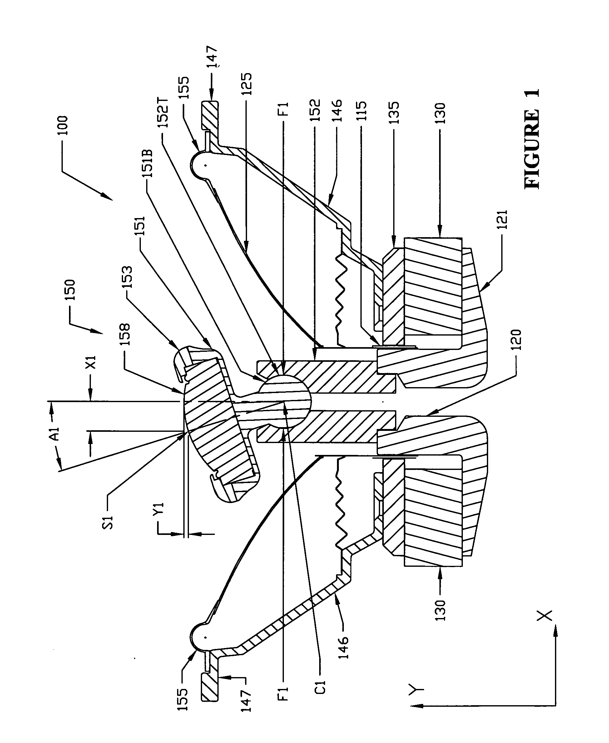
[0024]Referring to FIG. 1, shown is a typical prior art adjustable tweeter 158 positioned in the center vicinity of a woofer-audio transducer, partially shown by a magnet 130 positioned next to a pole 120, and connected to a back-plate 121 at its bottom and front-plate 135 at its top. Voice coil 115 is positioned in the electromagnetic field of a magnet 130 and in between the front-plate 135 and the pole 120. An electrical signal representing an audio signal is connected to the coil 115. The current of the electrical signal changes the relative physical position of the coil 115 with respect to the magnet 130 and in turn drives a diaphragm 125, which is connected to the coil 115. The diaphragm 125 displaces the air thereby reproducing an audible signal.

[0025]The pole 120 supports a tweeter mounting post 152, which supports a tweeter assembly 150. The tweeter assembly 150 comprises a tweeter holder 151, which further comprises a base 151B at its bottom end and a tweeter waveguide 153 ...


PUM


Abstract

An audio transducer assembly configured for positioning with respect to a mounting surface, said assembly employing a tweeter in a directionally adjustable body which swivels radially and axially for positioning and directing the tweeter in a desired direction. By keeping the center of rotation at or near the center of the surface of the tweeter, the adjustment of the tweeter does not significantly offset its body in the X or Y direction through its range of motion. Such configuration allows for compensation of the distortion caused by placing the tweeter in the middle of a woofer in a speaker having multiple transducers in a single assembly.

Description

I. FIELD[0001]The present disclosure is generally related to audio transducers used for sound generation and reproduction. More particularly, the present disclosure is directed to positionable audio speakers.II. DESCRIPTION OF RELATED ART[0002]Audio transducers (also known as and equivalently referred to as “speakers”) have been a staple of consumer and industrial electronics for some time. First introduced as sound delivery tools, the basic premise of such transducers is the movement of air or gas through a medium driven by a coil and a magnet. An electrical signal modulated by an audio signal changes the position of the coil about a magnet and drives the medium to move the air, thus reproducing the audio signal generated or captured at another location.[0003]As the audio transducer art progressed, it addressed the desire and need for higher quality reproduction. Stereo and multiple signal and audio transducer systems created a more realistic sound environment, adding direction and...

Claims


Application Information

Patent Timeline
Patent Type & Authority Applications(United States)
IPC IPC(8): H04R1/02
CPCH04R9/063H04R1/20
Inventor GLADWIN, TIMOTHY A.CARLISLE, CHRISTOPHER I.LUIMES, SHAWNJOHNSTON, ROBERT G.
Owner DEFINITIVE TECH
Why Eureka
Try Eureka