Vessel, system, and process for minimizing unequal flow distribution

a technology of unequal flow and valve, applied in the direction of hydrogen separation using solid contact, separation process, dispersed particle separation, etc., can solve the problems of reducing the performance of the adsorbent, non-uniformity that is generally undesirable, and unsatisfactory solutions, etc., to achieve constant cross-sectional area and low cost. , the effect of easy installation

Inactive Publication Date: 2010-12-30
UOP LLC
View PDF14 Cites 7 Cited by
  • Summary
  • Abstract
  • Description
  • Claims
  • Application Information

AI Technical Summary

Benefits of technology

[0005]Another exemplary embodiment may be a process for minimizing unequal flow distribution in a pressure swing adsorption system. The process can include positioning at least one spacer in a void volume of an adsorber vessel. Usually, the spacer forms a channel having a substantially constant cross-sectional area in a direction of a fluid flow.
[0007]The embodiments provided herein can provide a relatively inexpensive and easily installable spacer or insert inside the adsorber vessel. Preferably, the spacer can include at least one of a first part including a deflector and a second part including a diffuser. The deflector can form a substantial cone-shape with a base forming a polygon or a loop and parallel to a top side of an adsorbent bed. The diffuser can form an inverted funnel or a hemi-pseudosphere. The deflector can be nested with a diffuser to form at least one channel having a substantially constant cross-sectional area in a direction of fluid flow. Moreover, preferably the spacer may be centered about a vertical line passing through a middle of the adsorber vessel to make a smooth transition from an external pipe to the adsorbent bed. Typically, a small space is between the spacer and the adsorbent bed to allow gas to flow there-between. The inlet and outlet spacers can offset each other's flow mal-distribution due to the balance of the velocity heads during flow through the adsorbent bed.Definitions

Problems solved by technology

These void volumes, also referred to as a “non-selective volume”, can decrease the performance of the adsorbent.
Although adsorbent can be placed in the non-selective volume, such a solution is undesirable as it affects the distribution of gases through the adsorbent bed.
Desirably, the distribution is uniform, but placing adsorbent in the non-selective volume can create non-uniformity that is generally undesirable.

Method used


Image

  • Vessel, system, and process for minimizing unequal flow distribution
  • Vessel, system, and process for minimizing unequal flow distribution
  • Vessel, system, and process for minimizing unequal flow distribution

Examples


Embodiment Construction

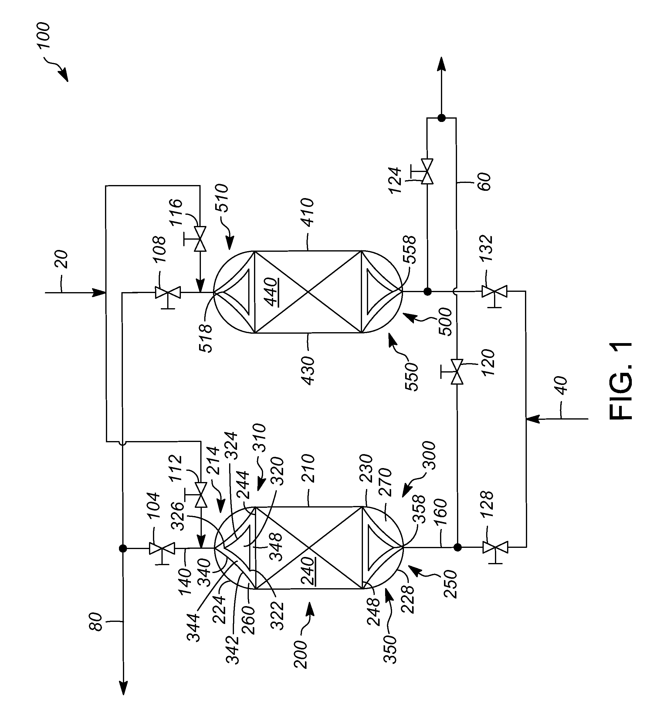
[0022]Referring to FIG. 1, an exemplary pressure swing adsorption system 100 can include a plurality of pressure swing adsorber vessels 200. Although a single adsorber vessel may be used, in this exemplary embodiment the system 100 can include a first pressure swing adsorber vessel 210 and a second pressure swing adsorber vessel 410.

[0023]Typically, the PSA process can be effectively similar to a “batch” process and the embodiments disclosed herein can fill void volumes to reduce recycling of fluids, such as gases. Generally, the pressure swing adsorption system 100 is operated on an adsorption cycle and a desorption cycle, optionally with each adsorber operating in offsetting adsorbing and desorbing cycles. Particularly, an incoming feed stream 20 can be provided as well as an incoming desorbent stream 40, such as a purge gas. Usually, one vessel is adsorbing while the other is desorbing.

[0024]Such adsorption systems may be utilized to purify hydrogen, but other gases may be purifi...


PUM

PropertyMeasurementUnit
volumeaaaaaaaaaa
void volumeaaaaaaaaaa
pressureaaaaaaaaaa

Abstract

One exemplary embodiment can be a pressure swing adsorber vessel. The pressure swing adsorber vessel can include one or more walls. Generally, the one or more walls contain an adsorbent bed having a first side and a second side and at least one spacer forming a cusp. Usually, the one or more walls and the adsorbent bed define at least one void volume adjacent to the adsorbent bed, and the cusp of the at least one spacer may be positioned in the at least one void volume. The cusp can be positioned opposing an incoming feed stream or a desorbent stream.

Description

FIELD OF THE INVENTION[0001]This invention generally relates to a vessel, system, and process for minimizing unequal flow distribution.DESCRIPTION OF THE RELATED ART[0002]Pressure swing adsorption (hereinafter may be abbreviated as “PSA”) processes can separate selectively adsorbable components, such as, carbon monoxide, carbon dioxide, methane, ammonia, hydrogen sulfide, argon, nitrogen, and water, from gas mixtures. Often, one or more of these components are adsorbed to purify a fluid stream, such as a hydrogen gas. Typically, a PSA process can include an adsorber that includes a vessel surrounding an adsorbent bed, including one or more adsorbent particles. Generally, a void space in the adsorber vessel can include spaces inside particles, spaces between particles, and internal spaces or void volumes defined by the walls of the vessel and the adsorbent bed.[0003]These void volumes, also referred to as a “non-selective volume”, can decrease the performance of the adsorbent. Althou...

Claims


Application Information

Patent Timeline
Patent Type & Authority Applications(United States)
IPC IPC(8): B01D53/047
CPCB01D53/0446B01J2208/00938B01D2253/104B01D2253/106B01D2253/108B01D2253/116B01D2256/16B01D2259/402B01J8/025C01B3/56C01B2203/043C01B2203/047C01B2203/0475C01B2203/0485C01B2203/0495B01J8/008B01J8/0278B01D53/047
Inventor SECHRIST, PAUL A.
Owner UOP LLC
Why Eureka
Try Eureka