Shell feed type gas separation membrane module

a gas separation membrane and shell feed technology, applied in the field of shell feed type can solve the problems of reducing the effective area of hollow fiber membranes and reducing the gas separation ability of the gas separation membrane modules, and achieves the effects of reducing the risk of tube sheet damage, simple structure and good gas separation efficiency

Inactive Publication Date: 2010-12-30
UBE IND LTD
View PDF8 Cites 36 Cited by
  • Summary
  • Abstract
  • Description
  • Claims
  • Application Information

AI Technical Summary

Benefits of technology

[0025]The present invention can reduce the risk of the tube sheet is damage due to a pressure applied to the tube sheet in a membrane module, without increase in a thickness of a tube sheet, with a simple structure. A gas separation membrane module of the present invention exhibits a good gas separation efficiency without decrease in an effective ar

Problems solved by technology

Increase in a thickness of tube sheet 102, however, reduces an effective area of hollow fiber me

Method used


Image

  • Shell feed type gas separation membrane module
  • Shell feed type gas separation membrane module
  • Shell feed type gas separation membrane module

Examples


experimental example 1-1

[0123]Example 1-1 is an experiment in which using a gas separation membrane module having a structure described with reference to FIGS. 5 to 9, the presence of damage to tube sheet 2 was determined when tube sheet 2 received a pressure in the reverse direction to that applied during operation.

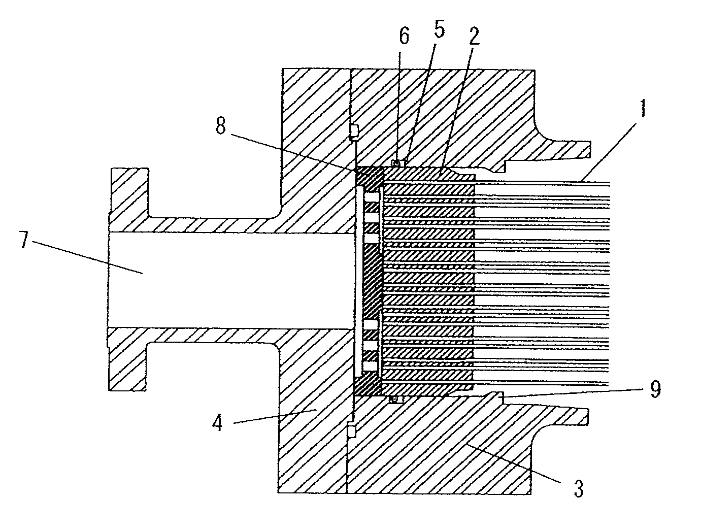
[0124]The hollow fiber element had, as shown in FIG. 5, hollow fiber membranes 1, tube sheet 2 in which the ends of hollow fiber membranes 1 were embedded, core tube 14 which was disposed along hollow fiber membranes 1 and held on tube sheet 2, auxiliary member 13 disposed in the outer surface of tube sheet 2, perforated plate 8 attached to auxiliary member 13, and a stopper attached to auxiliary member 13. Hollow fiber membrane 1 was made of a polyimide. Core tube 14 was made of an aluminum alloy. Tube sheet 2 was made of an epoxy resin having a size of 250 mm (diameter)×85 mm (thickness). Auxiliary member 13, perforated plate 8 and stopper 9 were made of stainless steel, and perforated plate ...

experimental example 1-2

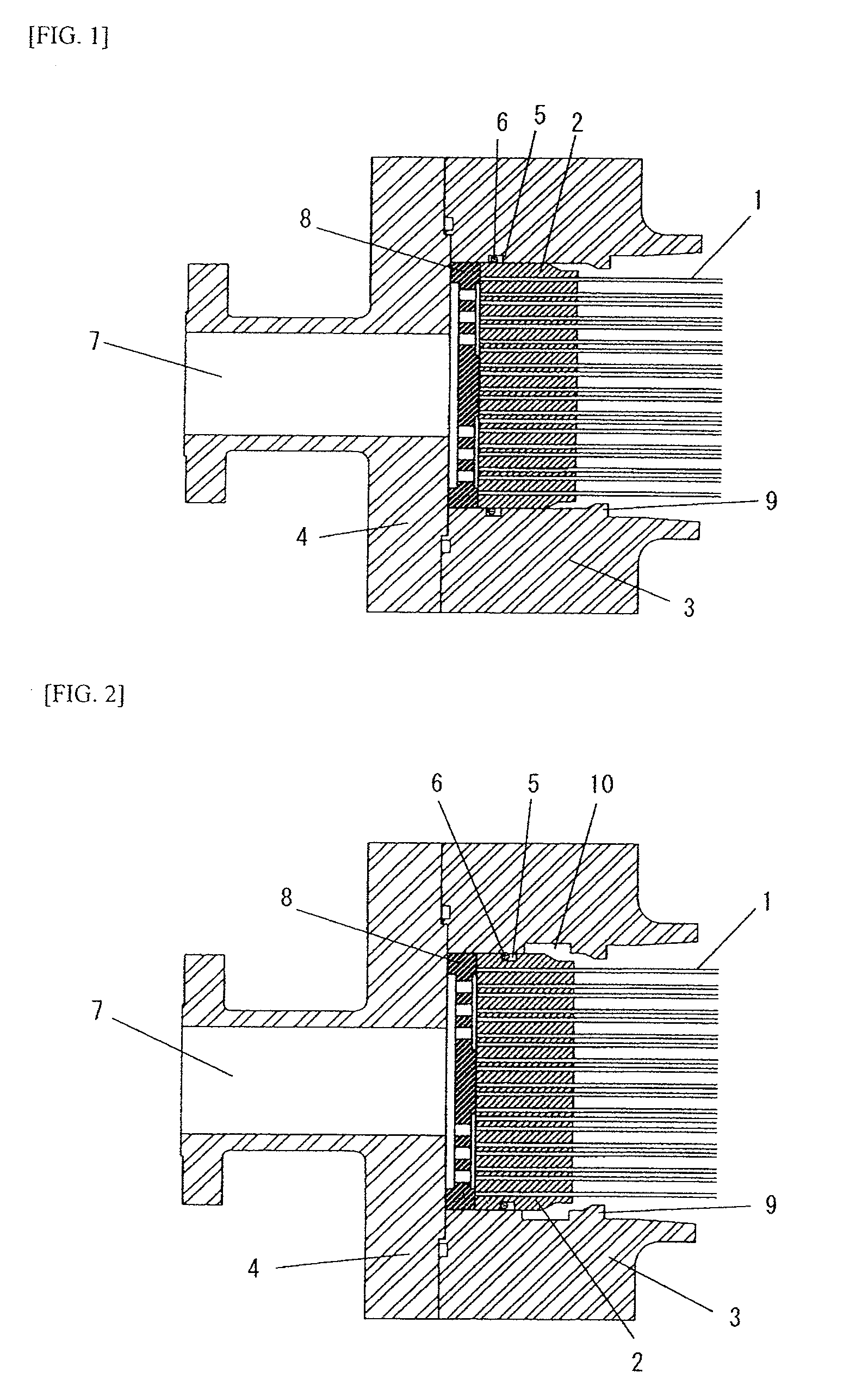
[0128]In Experimental Example 1-2, a pressure causing damage to tube sheet 2 when tube sheet 2 received a pressure in the reverse direction to that applied during normal operation was determined as described in Example 1, using a gas separation membrane module constructed as described in Experimental Example 1-1 except that tube sheet 2 was immovably mounted in vessel body 3 as shown in FIG. 10. As a result, damage to tube sheet 2 was observed when compressed air was fed from permeate gas outlet 7 at a pressure of 3 MPa (gauge pressure).

Gas Separation Performance Experiment:

[0129]Then, an experiment for gas separation performance was conducted.

experimental example 2-1

[0130]In Experimental Example 2-1, a hollow fiber element was inserted into vessel body 3 having mixed gas inlet 19 and core tube holding part 18 as shown in FIG. 8 through its opening, and then the opening of vessel body 3 was closed by lid 4 to prepare a gas separation membrane module. The hollow fiber element had a hollow fiber bundle consisting of polyimide asymmetric hollow fiber membranes (P′O2 / P′N2=6.5) with a membrane area of 80 m2, an epoxy resin tube sheet to which the hollow fiber bundle was bonded and a core tube attached to the tube sheet, and the periphery of the hollow fiber bundle was wrapped by a polyimide film member. A perforated plate was disposed, contacting the tube sheet. The perforated plate was made of stainless steel and 64 perforations with a diameter of 12 mm were pre-formed in the perforated plate. Furthermore, in the surface of the perforated plate contacting the tube sheet, a permeate gas flow path consisting of a concave portion with a depth of 3 mm w...


PUM


Abstract

A gas separation membrane module has a vessel housing a hollow fiber element including a hollow fiber bundle consisting of a number of hollow fiber membranes (1) and a tube sheet (2) holding one end of the hollow fiber bundle. The interior of the vessel is partitioned by the tube sheet (2) into two spaces consisting of a raw gas chamber and a permeate gas chamber. A high-pressure mixed gas is fed into the raw gas chamber where gas separation is carried out. The gas separation membrane module has a configuration where during operation, the tube sheet (2) is supported by means of a perforated plate (8) in the vessel by a pressure from the mixed gas fed to maintain airtightness between the two spaces and when the tube sheet (2) receives a pressure in the reverse direction to that applied during the operation of the gas separation membrane module, the tube sheet (2) is forced to move within the vessel by the pressure in the reverse direction, thereby losing airtightness between the two spaces.

Description

TECHNICAL FIELD[0001]The present invention relates to a shell feed type gas separation membrane module for separating gases while feeding a high-pressure gas into an outer space of a hollow fiber membrane in a vessel.BACKGROUND ART[0002]Gas separation membrane modules have been used in various applications because they are small and can easily separate gases by simple operation in comparison with other separating means. Gas separation can be conducted by introducing a mixed gas into a gas separation membrane module where the gas is separated into a permeate gas which has permeated the membrane and a non-permeate gas which has not permeated the membrane. The interior of the gas separation membrane module is partitioned into two spaces by the gas separation membrane. Since a gas flow rate through the gas separation membrane is proportional to a pressure difference between these two spaces (a partial pressure difference for each gas component), the mixed gas fed to the gas separation m...

Claims


Application Information

Patent Timeline
IPC IPC(8): B01D53/22
CPCB01D53/22B01D2313/02B01D63/024B01D63/02
Inventor NAKAMURA, TOMOHIDETANIHARA, NOZOMUNAKANISHI, SHUNSUKE
Owner UBE IND LTD
Why Eureka
Try Eureka