Lubrication and sealing system for internal combustion engine

a technology for sealing systems and internal combustion engines, which is applied in the direction of machines/engines, mechanical equipment, auxiliaries, etc., can solve the problems of parts and machining operations adding undesirable cost, weight, complexity, etc., and achieve the effect of avoiding additional costs

Active Publication Date: 2010-12-30
FORD GLOBAL TECH LLC
View PDF14 Cites 8 Cited by
  • Summary
  • Abstract
  • Description
  • Claims
  • Application Information

AI Technical Summary

Benefits of technology

[0012]It is an advantage of a lubrication and sealing system according to the present disclosure that lubricant may be provided to a portion of an engine, for example, outlying the cylinder head and cylinder block, with an extension of the cylinder head gasket, and without the need for any additional componentry.
[0013]It is another advantage of a lubrication and sealing system according to the present disclosure that additional cost is avoided by eliminating the need for machining operations such as boring, drilling and tapping which would otherwise be required for mounting an oil nozzle to a pressure lubrication system of a machine such as an engine.

Problems solved by technology

These added parts and machining operations add undesirable cost, weight, and complexity to the engine or other machine.

Method used


Image

  • Lubrication and sealing system for internal combustion engine
  • Lubrication and sealing system for internal combustion engine
  • Lubrication and sealing system for internal combustion engine

Examples


Embodiment Construction

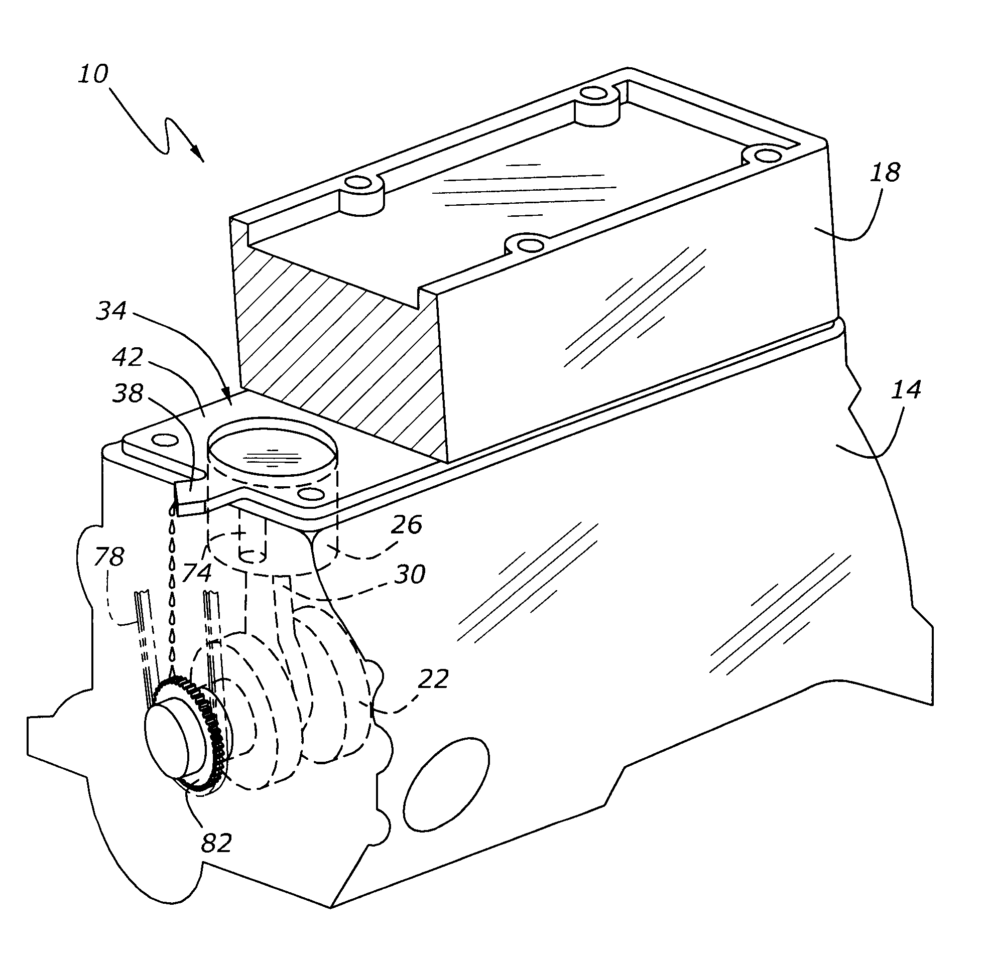
[0017]As shown in FIG. 1, an engine, 10, has a cylinder block 14, and a cylinder head 18. Crankshaft 22 and piston and connecting rod 26 and 30 are mounted within cylinder block 14. A cylinder head gasket, 34, extends between cylinder block 14 and cylinder head 18. A lubrication passage 74 (FIG. 1) is located near the front of cylinder block 14, and provides oil under pressure from an oil pump (not shown), of the type usually employed in internal combustion engines for providing higher pressure oil to the engine's bearings and other wear surfaces. If desired, a source of higher pressure oil may be configured as an oil passage within cylinder head 18, as an alternative to illustrated oil passage 74. Gasket 34 has a nozzle portion, 38, which is cantilevered outwardly from cylinder block 14 and cylinder head 18, and which provides lubrication to a timing chain, 78, as well as to a crankshaft sprocket, 82.

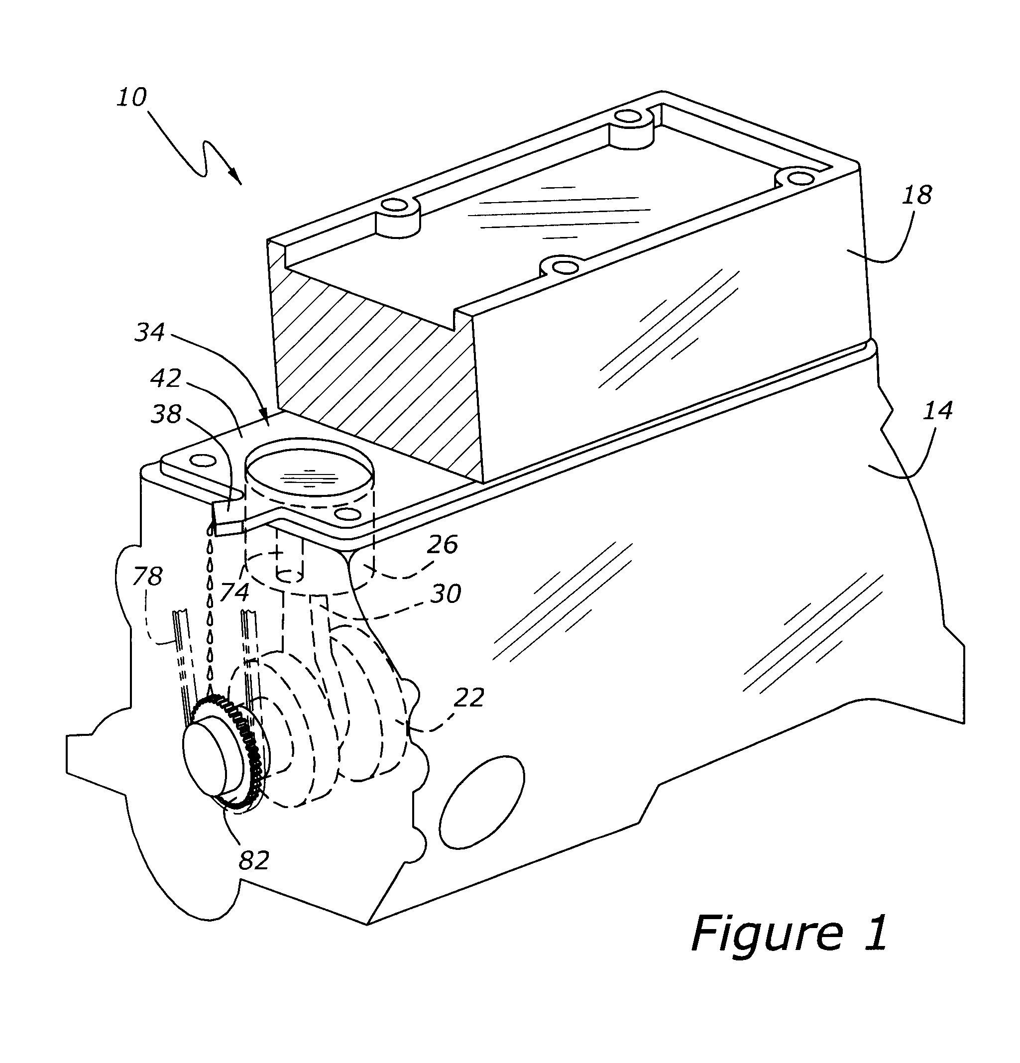
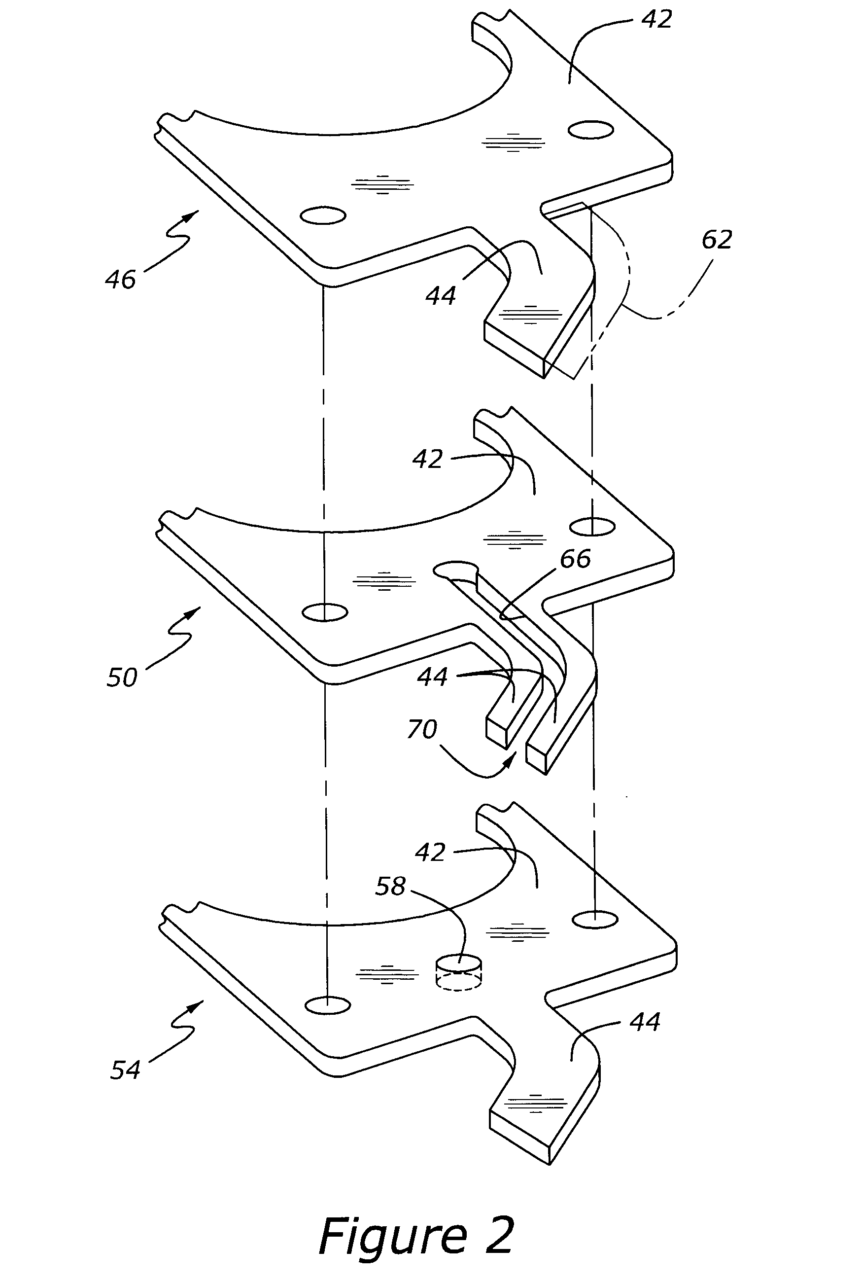
[0018]Turning now to FIG. 2, the multilayer construction of the present lubricatio...


PUM


Abstract

A sealing and lubrication system includes first and second machine components with a combination sealing and lubrication directing gasket mounted between the first and second machine components. The gasket includes a sealing portion extending between the components and a nozzle portion which is operatively connected with the sealing portion as well as with a lubrication supply passage. The nozzle portion extends from the sealing portion of the gasket to a region external to the first machine component and the second machine component. The nozzle provides lubricating oil to at least one moving part of a third machine component.

Description

BACKGROUND OF THE DISCLOSURE[0001]1. Field of the Disclosure[0002]The present disclosure relates to a combination sealing and lubrication directing gasket for use in a machine such as an internal combustion engine.[0003]2. Related Art[0004]Machines such as internal combustion engines, which are assembled with relatively rigid parts having gaskets clamped therebetween, often utilize pressure lubrication, so as to provide lubrication not only at higher pressure to bearings, but also at pressures approaching atmospheric pressure to components such as gear drives and chain drives commonly employed, for example, to power the cylinder valve operating gear of an engine. Provision of this type of spray lubrication is frequently provided by means of a discrete nozzle which is mounted to a cylinder block or cylinder head and directed into the case of an engine, often behind a front cover, so as to provide lubrication to the engine's valve drive system. Known nozzles require special machining ...

Claims


Application Information

Patent Timeline
Patent Type & Authority Applications(United States)
IPC IPC(8): F01M1/02F02F11/00
CPCF01M9/08F01M9/108F16J15/0825F01M2011/021F16J15/064F01M11/02
Inventor REINHART, PAUL T.BRENKUS, MARKFEDESON, KEN
Owner FORD GLOBAL TECH LLC
Why Eureka
Try Eureka