Bonded Assembly Having Low Residual Stress

a technology of residual stress and bonded assemblies, which is applied in the direction of machines/engines, mechanical equipment, manufacturing tools, etc., can solve the problems of thermal stress vulnerability of such cutters, inability to absorb impact energy, and too thin metal interlayers to achieve high impact tools, rapid heating, and rapid heating

Inactive Publication Date: 2010-12-30
SCHLUMBERGER TECH CORP
View PDF105 Cites 53 Cited by
  • Summary
  • Abstract
  • Description
  • Claims
  • Application Information

AI Technical Summary

Benefits of technology

[0006]In one aspect of the present invention, a method for forming a bonded assembly comprises providing a first and second portion of the assembly; preparing a mating surface on each portion that conforms substantially to the mating surface of the other portion; rapidly heating a bonding material while substantially heating no more than a thin surface zone adjacent each mating surface, and rapidly assembling the two portions in such a manner as to confine a fraction of the bonding material between the mating surfaces.
[0007]A typical application for such a bonded assembly is a high impact tool. Typically the first portion of the tool comprises a hard material, preferably a material such as thermally stable polycrystalline diamond, and the second portion comprises a strong support material, preferably cobalt-cemented tungsten carbide. The tool may comprise a working surface that is substantially pointed, substantially dome shaped, substantially cylindrical, or substantially flat.
[0008]The bonding material may comprise any combi

Problems solved by technology

A metal interlayer that is too thin is not capable of absorbing impact energy, and a metal interlayer that is too thick may allow the TSP diamond to fracture from bending stress.
Although it doe

Method used


Image

  • Bonded Assembly Having Low Residual Stress
  • Bonded Assembly Having Low Residual Stress
  • Bonded Assembly Having Low Residual Stress

Examples


Embodiment Construction

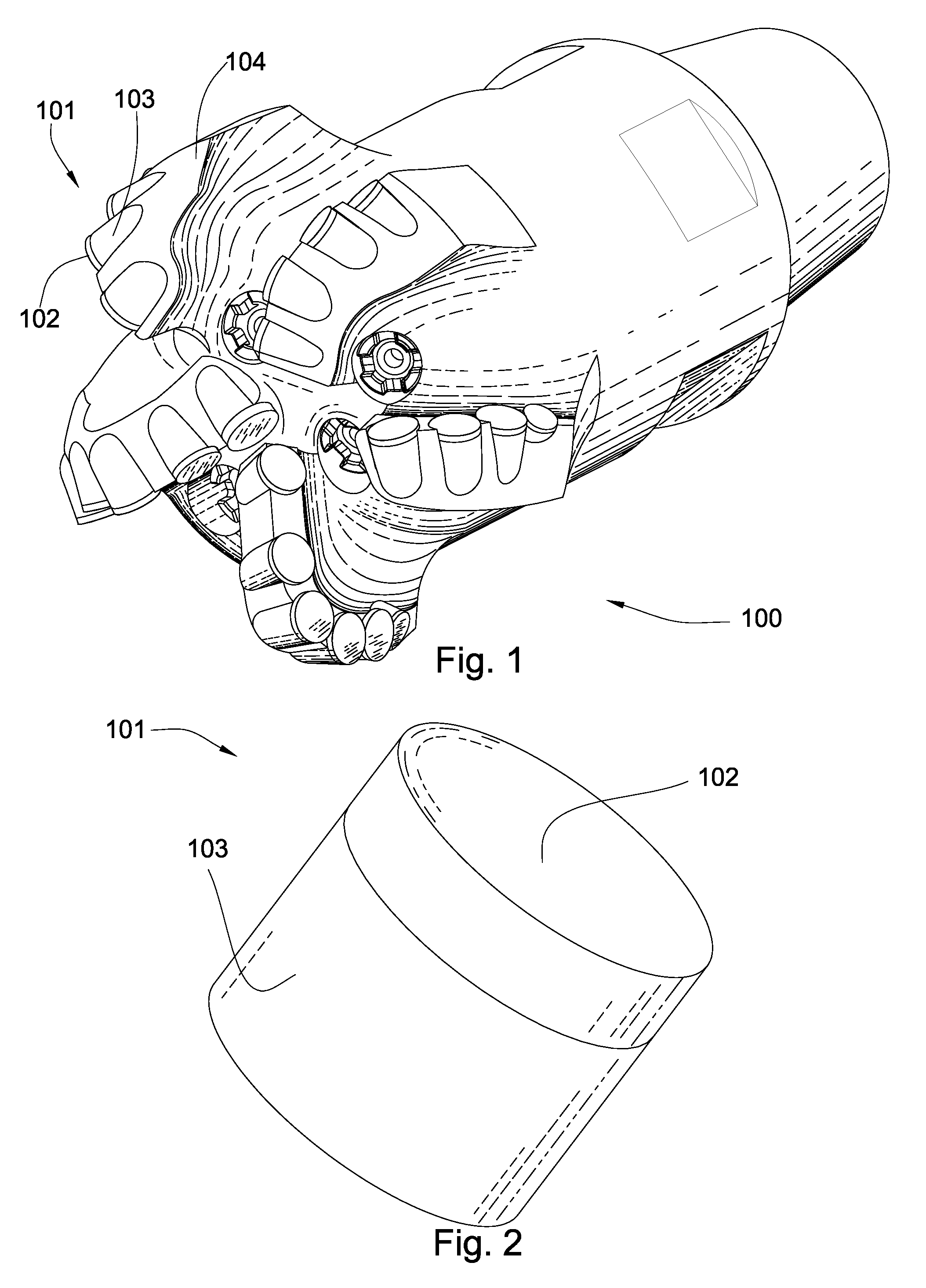
[0019]Referring now to the figures, FIG. 1 discloses a rotary shear bit 100 comprising high impact tools 101. High impact tools 101 may comprise a polycrystalline diamond, cubic boron nitride, or other super-hard material layer 102 and a cemented metal carbide substrate 103. High impact tools 101 may be pressed into pockets on the bit body 104, may be brazed to pockets in the bit body 104, or may be attached by another method, including the method of the present invention.

[0020]Many prior art high impact tools comprise a polycrystalline diamond layer and a cemented metal carbide substrate sintered together in a high pressure, high temperature press. The polycrystalline diamond bonds to the carbide substrate at a temperature sufficient to melt the binder / catalyst material and at a pressure sufficient to maintain the thermodynamic stability of the diamond. Since the carbide substrate has a higher coefficient of thermal expansion than polycrystalline diamond, the carbide will contract ...


PUM

PropertyMeasurementUnit
Contact angleaaaaaaaaaa
Temperatureaaaaaaaaaa
Electrical resistanceaaaaaaaaaa

Abstract

In one aspect of the present invention, a method for forming a bonded assembly comprises providing a first and second portion of the assembly; preparing a mating surface on each portion that conforms substantially to the mating surface of the other portion; rapidly heating a bonding material while substantially heating no more than a thin surface zone adjacent each mating surface, and rapidly assembling the two portions in such a manner as to confine a fraction of the bonding material between the mating surfaces. The first portion may comprise polycrystalline diamond or thermally stable polycrystalline diamond; the second portion may comprise cobalt-cemented tungsten carbide. The assembly may comprise a tool for high-impact applications.

Description

BACKGROUND OF THE INVENTION[0001]This invention relates to providing a strong thermally-actuated bond between two parts in such a manner that only a thin zone within each part near the bond is heated to any significant degree. A braze or weld material may be employed as a separate small body. The process provides a bonded assembly having low residual stress and is especially useful for bonding dissimilar materials. Such an assembly is particularly useful for tools such as are used in earth boring drill bits, asphalt degradation equipment, and any application that may be subject to high impact forces and high temperatures.[0002]Efforts to lengthen the life of such tools by reducing internal stress are disclosed in the prior art. U.S. Pat. No. 7,487,849 to Radtke discloses a cutting element and a method for making the same. The cutting element includes a substrate, a Thermally Stable Polycrystalline (TSP) diamond layer, a metal interlayer between the substrate and the diamond layer, a...

Claims


Application Information

Patent Timeline
IPC IPC(8): E21B10/573B23K20/00B29C65/02B29C65/16B29C65/06B23K20/12B23K13/01
CPCE21B10/5735B23K20/023
Inventor HALL, DAVID R.HALL, JR., H. TRACY
Owner SCHLUMBERGER TECH CORP
Why Eureka
Try Eureka