Sampling/Quantization Converters

Active Publication Date: 2010-12-30
PAGNANELLI FAMILY TRUST
View PDF25 Cites 43 Cited by
  • Summary
  • Abstract
  • Description
  • Claims
  • Application Information

AI Technical Summary

Benefits of technology

[0021]Such an apparatus typically can provide a better combination of high resolution and wide bandwidth than is possible with conventional converters and can be used for var

Problems solved by technology

However, the present inventor has discovered that each of the presently existing approaches exhibits shortcomings that limit overall performance at very high sample rates.
However, existing solutions are limited by instantaneous bandwidth (effective sample rate), effective conversion resolution (number of effective bits), or both.
When a continuous-time continuously variable signal is converted into a discrete-time discretely variable signal through sampling and quantization, the quality of the signal degrades because the conversion process introduces quantization, or rounding, noise.
However, the resolution of flash converters can be limited by practical implementation impairments that introduce quantization errors, such as clock jitter, thermal noise, and rounding/gain inaccuracies caused by component tolerances.
Although flash converters potentially could realize up to 9 bits of resolution at instantaneous information bandwidths greater than 10 GHz, this potential has been unrealized in commercial offerings.
However, pipeline converters typically can provide less than about 1 GHz of instantaneous bandwidth.
Conventional oversampling converters can offer very high resolution, but the noise filtering and signal reconstruction process generally limits the utility of oversampling converters to applications requiring only low instantaneous bandwidth.
These disadvantages, which are discussed in greater detail in the Description of the Preferred Embodiment(s) section, include: (1) use of delta-sigma modulation (Galton, Aziz, and Beydoun) impairs high-frequency operation because the sample-and-hold operation limits the performance of DT DSMs and non-ideal circuit behavior can degrade the noise-shaping response and stability

Method used


Image

  • Sampling/Quantization Converters
  • Sampling/Quantization Converters
  • Sampling/Quantization Converters

Examples


Example

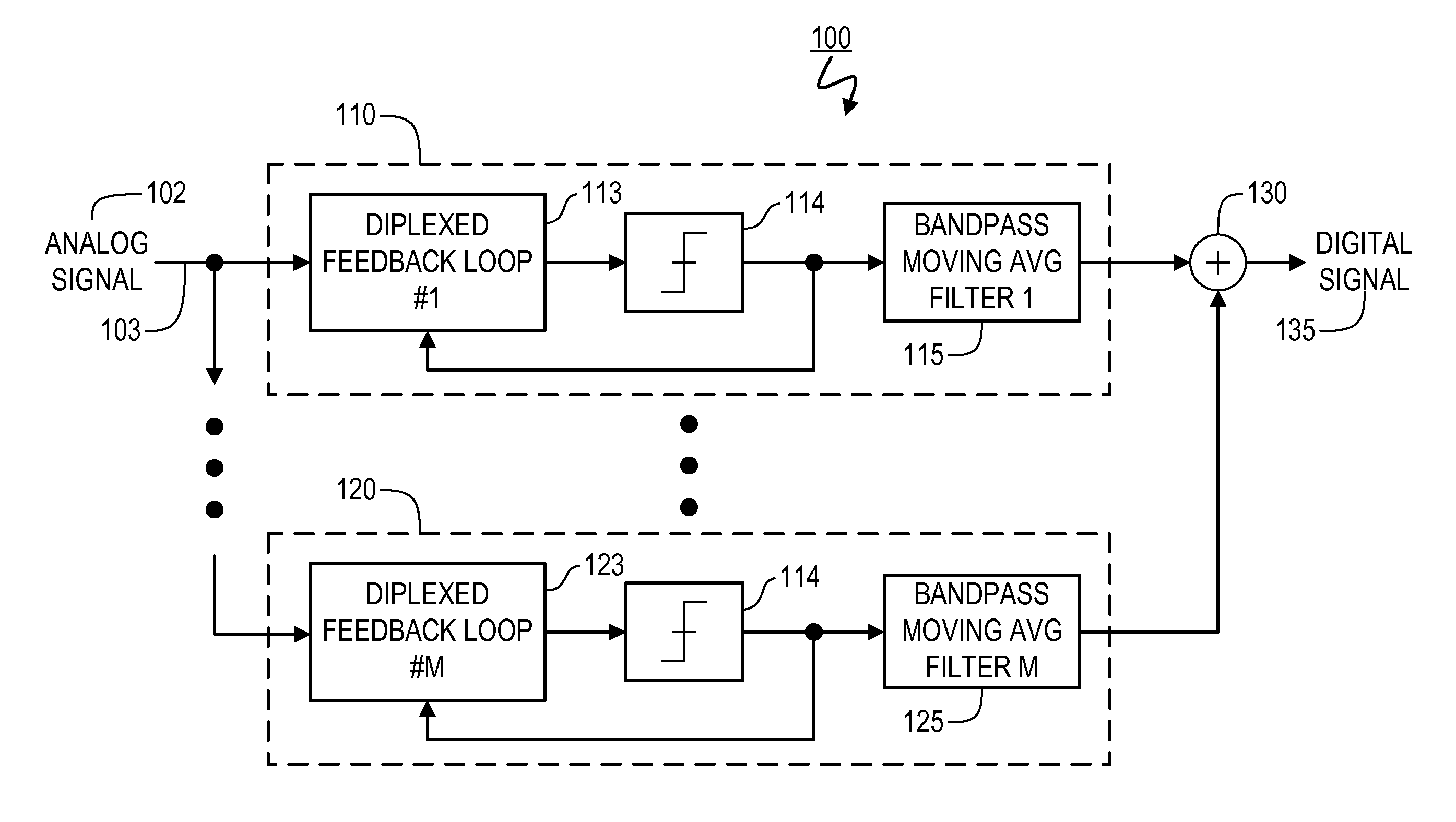
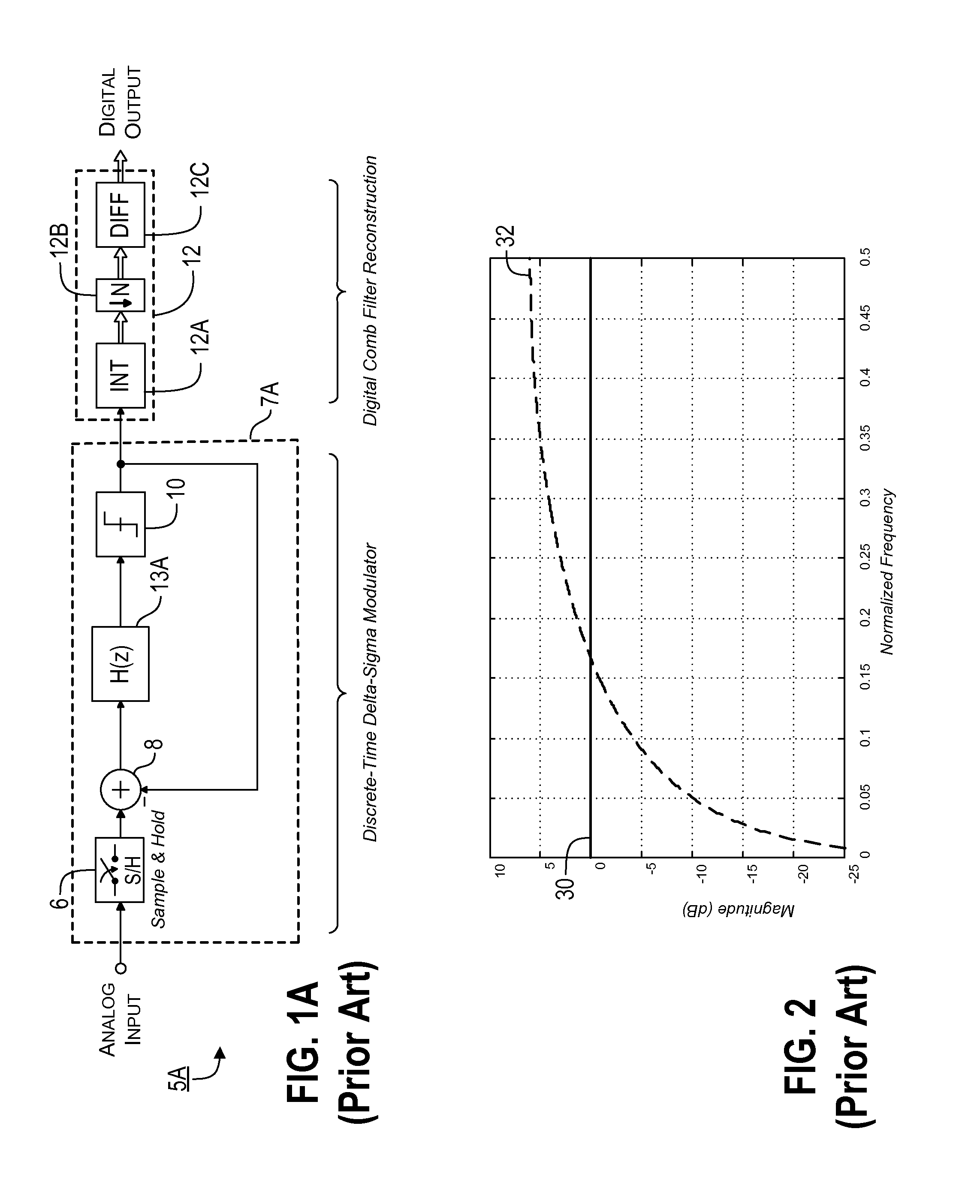
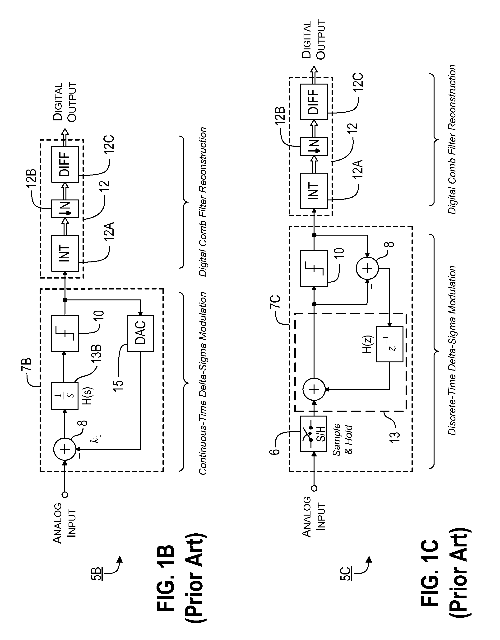
[0043]A preferred converter according to the present invention uses a technique that sometimes is referred to herein as Multi-Channel Bandpass Oversampling (MBO). Such a technique shares some structural similarities with conventional parallel delta-sigma (ΠΔΣ) and multi-band delta-sigma (MBA) analog-to-digital converters, in that the MBO converter also consists of multiple, parallel, oversampling converters. However, an MBO converter according to the preferred embodiments of the present invention incorporates one or more of the following technological innovations to improve instantaneous bandwidth and resolution: (1) continuous-time, Diplexed Feedback Loops (DFLs) are used in place of delta-sigma modulators, e.g., to improve quantization noise shaping at very high converter sample rates; (2) bandpass (preferably second-order or higher) oversampling eliminates the need for analog downconversion using sinusoidal waveforms or Hadamard sequences (e.g., as in ΠΔΣ converters); (3) Moving ...


PUM


Abstract

Provided are, among other things, systems, methods and techniques for converting a continuous-time, continuously variable signal into a sampled and quantized signal. According to one representative embodiment, an apparatus includes multiple quantization-noise-shaping continuous-time filters, each in a separate processing branch and having an adder that includes multiple inputs and an output; an input signal is coupled to one of the inputs of the adder; the output of the adder is coupled to one of the inputs of the adder through a first filter; and the output of a sampling/quantization circuit in the same processing branch is coupled to one of the inputs of the adder through a second filter, with the second filter having a different transfer function than the first filter.

Description

[0001]This application claims the benefit of U.S. Provisional Patent Application Ser. No. 61 / 221,009, filed on Jun. 26, 2009, and titled “Method of Linear to Discrete Signal Transformation using Orthogonal Bandpass Oversampling (OBO)”, and U.S. Provisional Patent Application Ser. No. 61 / 290,817, filed on Dec. 29, 2009, and titled “Sampling / Quantization Converters”. Both applications are incorporated by reference herein as though set forth herein in full.FIELD OF THE INVENTION[0002]The present invention pertains to systems, methods and techniques for converting a continuous-time continuously variable signal into a sampled, quantized discrete-time signal, and it is particularly applicable to very high sample-rate data converters with high instantaneous bandwidth.BACKGROUND[0003]Many applications in modern electronics require that continuous-time signals be converted to discrete signals for processing using digital computers and signal processors. Typically, this transformation is made...

Claims


Application Information

Patent Timeline
IPC IPC(8): H03M3/00
CPCH03M3/468H03M3/436
Inventor PAGNANELLI, CHRISTOPHER
Owner PAGNANELLI FAMILY TRUST
Why Eureka
Try Eureka