Connection device

Active Publication Date: 2010-12-30
SOFUKEN
View PDF7 Cites 4 Cited by
  • Summary
  • Abstract
  • Description
  • Claims
  • Application Information

AI Technical Summary

Benefits of technology

[0011]The invention disclosed in Patent Document 2 is an invention relating to a coupling metal fitting for connecting a longitudinal cross piece of a glass panel to a lateral cross piece thereof. In the coupling metal fitting, a locking claw of the coupling metal fitting disposed in the lateral cross piece is locked into a groove of the longitudinal cross piece and the lateral cross piece is fixed to the longitudinal cross piece in this state. It is assumed that a configuration of the coupling metal fitting is relatively simple and the longitudinal cross piece and the lateral cross piece can be assembled very easily. However, a locking strength of the locking claw to the longitudinal cross piece eventually depends on an elastic force of an arm abutted against the longitudinal cross piece so as to push it. Therefore, there are assumed such circumstances that when the elastic force of the arm is increased to increase the locking force, the locking claw inserted into a cutout formed in the longitudinal cross piece comes into pressure contact with the groove and makes it difficult or impossible to move the lateral cross piece to a predetermined attachment position. When the elastic force of the arm is weakened to ease the movement on the contrary, the locking strength of the locking claw is reduced. Thus, the invention has antinomy.
[0015]The present invention provides a highly versatile connection device characterized in that it has a simple structure and a high connecting strength which can be adjusted when necessary and further can optionally set an attachment position to a target to be attached.

Problems solved by technology

However, the invention has a bottleneck in that a connecting member is large and as high as the vertical length of the panels, a structure is complex, and further a connection is made tentatively in any case and a coupling work is additionally required.
Therefore, there are assumed such circumstances that when the elastic force of the arm is increased to increase the locking force, the locking claw inserted into a cutout formed in the longitudinal cross piece comes into pressure contact with the groove and makes it difficult or impossible to move the lateral cross piece to a predetermined attachment position.
However, the coupler has many complex components and does not have versatility because it is dedicated for coupling of only panels.
Although Patent Document 5 is most simply configured in Patent Documents described above, it is naturally inferior in workability because many bolts are screwed one by one.

Method used


Image

  • Connection device
  • Connection device
  • Connection device

Examples


embodiment 1

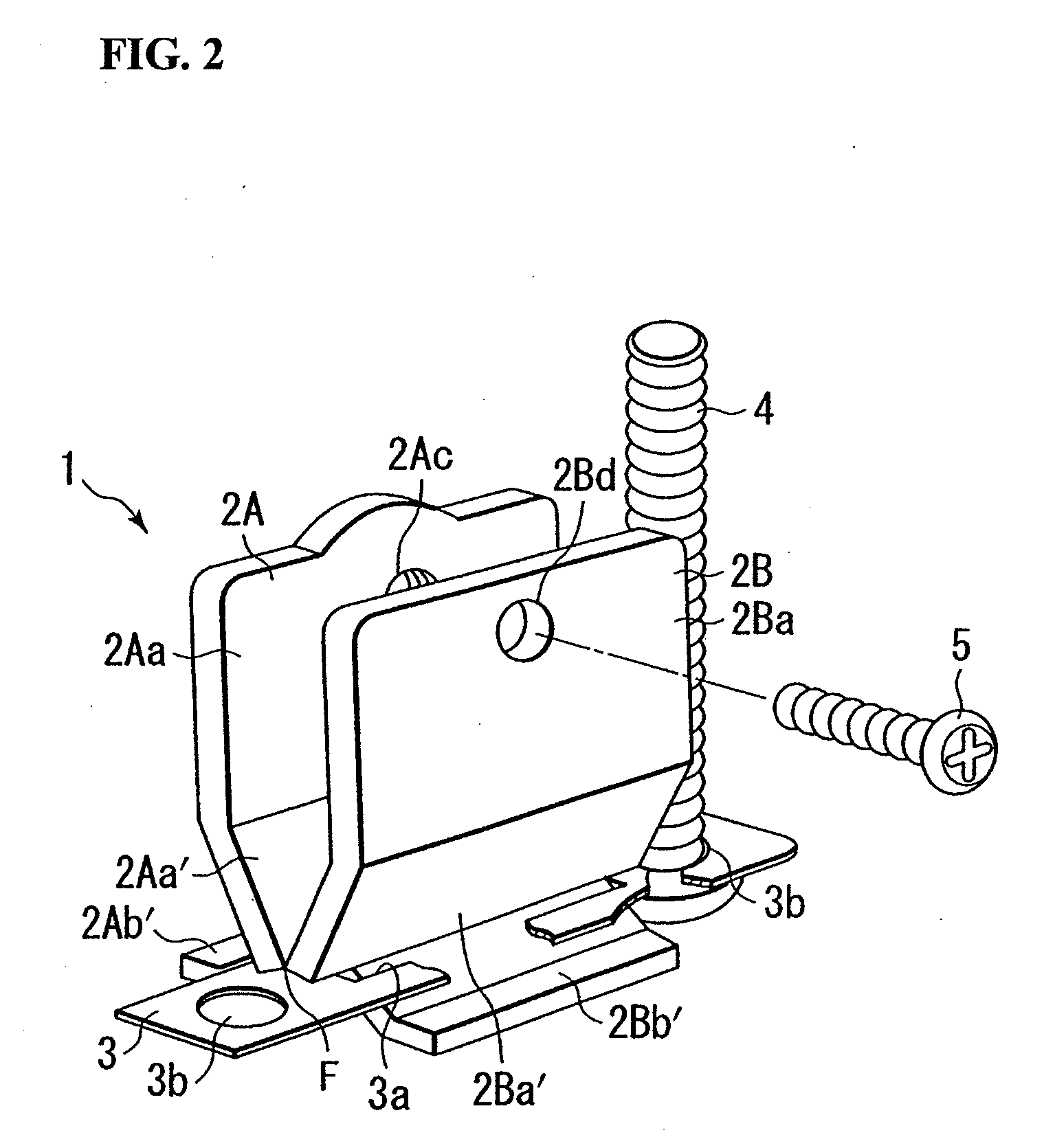
[0037]FIG. 2 shows a first embodiment of the invention. Note that the same portions as those shown in FIG. 1 are denoted by the same reference numerals.

[0038]Lever members 2A, 2B constituting an illustrated connection device 1 are composed of a metal such as steel or aluminum, or may be composed of a material other than the metal such as plastic as long as it has the same strength as the metal.

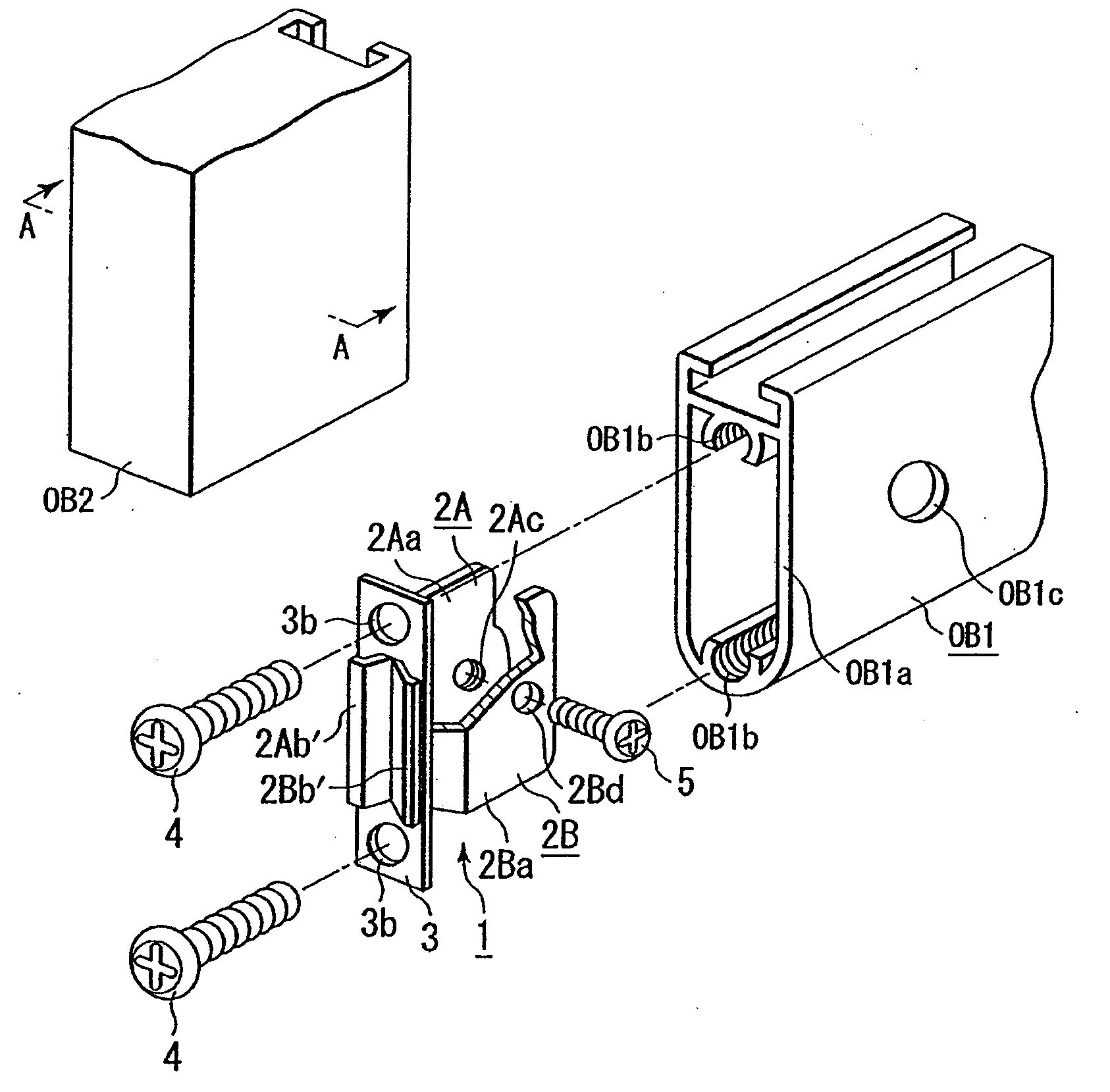
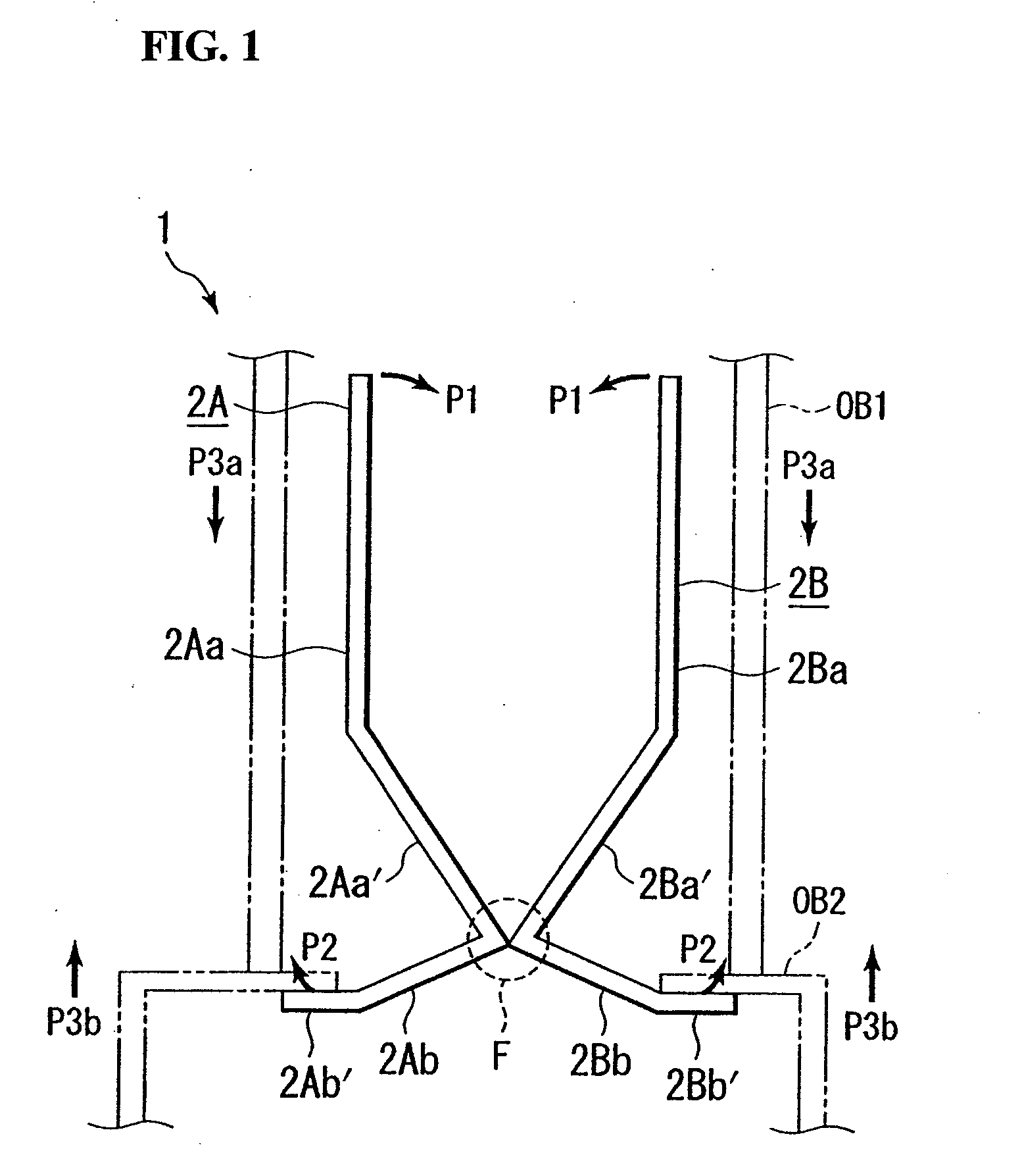
[0039]As shown also in FIG. 1, the lever members 2A, 2B reach bent portions, which constitute a fulcrum portion F, through confronting power application portions 2Aa, 2Ba and slope portions 2Aa′, 2Ba′ where both the power application portions 2Aa, 2Ba are located close to each other. Reference numeral 3 denotes a member for constituting the fulcrum F (hereinafter, called “fulcrum member”). As shown in FIG. 2, the fulcrum member 3 is a plate member in which a long hole 3a is formed at a center in a longitudinal direction so that the bent portions, where the lever members 2A, 2B are abutted with...

embodiment 2

[0055]FIGS. 6 to 7C show a second embodiment.

[0056]The embodiment has a main feature in that a drive means, which causes lever members 2A and 2B to approach each other and separate from each other, is configured differently from the configuration of the above embodiment.

[0057]Reference numeral 8 denotes a pin (hereinafter, called “drive pin”) disposed in the lever members 2A and 2B to drive them, and one end of the drive pin 8 is configured as a pin head 8a locked to the lever member 2A side. In contrast, a pin insertion hole 2Be having the same configuration as that of the screw insertion hole 2Bd is formed in the lever member 2B. A shaft 9, which is inserted into the pin 8 orthogonal thereto, is disposed in the portion of the pin 8 projecting to the outside of the lever member 2B from the pin insertion hole 2Be, and a lever 10 is attached to the shaft 9 so that the lever 10 can rotate about the shaft 9.

[0058]A cam portion 10a is formed in a portion of the lever 10 in contact with ...

embodiment 3

[0066]FIGS. 8A and 8B show a third embodiment of the invention.

[0067]In the embodiment, a combination of the lever members 2A, 2B and a configuration of a drive means of both the lever members 2A, 2B are mainly different from those of the embodiments described above.

[0068]First, both the lever members 2A, 2B intersect with each other in a fulcrum portion F by a hinge structure or the like, and a locking portion 2Ab′ of the lever member 2A is located below the lever member 2B and a locking portion 2Bb′ of the lever member 2B is located below the lever member 2A. Therefore, a force P2 is generated in the locking portions 2Ab′, 2Bb′ by separating power application portions 2Aa, 2Ba of both the lever members from each other (state of FIG. 8B) and is eliminated by causing both the power application portions 2Aa, 2Ba to approach each other on the contrary (state of FIG. 8A).

[0069]Note that although the drive means of the embodiments 1 and 2 can be used as it is as a drive means for execut...


PUM


Abstract

A connection device for detachably and strongly fixing two connection target members has two confronting lever members configured to swing about a fulcrum member, a screw hole formed in the lever member of the confronting lever members and an insertion hole, through which a screw passes, formed in the other lever member. Both the lever members are caused to approach each other by screwing the screw into the screw hole so that locking portions of the lever members are displaced so as to be moved upward through the fulcrum member constituting a fulcrum portion. A fixing device main body is fixed to one of connection target members by a screw passing through the fulcrum member and the locking portions are locked to the other connection target member.

Description

BACKGROUND OF THE INVENTION[0001]The present invention relates to a connection device, and more particularly to a connection device configured such that it can simply and strongly connect and fix a predetermined body to an attachment target using a principle of lever and easily release a connected and fixed state.[0002]As a method of connecting a body for the purpose of connecting a particular body to a particular target, there are various methods such as a method using a bonding agent, a method using nails and screws and a method of interposing a connecting member such as a metal fitting, welding of metal to metal or to other material, blazing, and the like. However, since these connecting methods are semi-permanent and fixed connecting methods, when a connected state is released, these members are so damaged that they cannot be reused in any cases.[0003]When components such as houses, furniture, and various types of structures are semi-permanently integrally connected, the connect...

Claims


Application Information

Patent Timeline
IPC IPC(8): F16B1/00
CPCE04B2/766F16B2/10F16B5/0607Y10T403/24F16B12/02F16B12/32F16B7/04
Inventor KOMAMURA, TAKEO
Owner SOFUKEN
Why Eureka
Try Eureka