
Inlet Guide Vane for a Gas Compressor

a gas compressor and guide tube technology, applied in mechanical equipment, machines/engines, liquid fuel engines, etc., can solve the problems of acting elements still being exposed to wear and systems particularly vulnerable to mechanical failure, and achieve the effect of improving reliability and reducing mechanical wear

Inactive Publication Date: 2010-12-30
SIEMENS AG
View PDF12 Cites 20 Cited by
  • Summary
  • Abstract
  • Description
  • Claims
  • Application Information

AI Technical Summary

Benefits of technology

"The present invention provides an adjustable inlet guide vane for a compressor that improves reliability and reduces mechanical wear. The vane is made of electroactive polymers (EAPs) that change their shape when voltage is applied, allowing for easy electronic control of the vane properties. The use of EAPs simplifies the vane design and reduces the amount of mechanical parts needed. The fixed portion of the vane can be located at the fore side or between two portions, and the vane can be covered with a flexible coating layer for protection and noise reduction. The compressor, turbocharger, and gas turbine comprising the adjustable inlet guide vane are also provided."

Problems solved by technology

However, such arrangements require a number of moving parts, such as the actuators, rings, and linkage, which are subject to mechanical stress, wear, and environmental interferences, thus making such systems particularly vulnerable to mechanical failure.
While this solution reduces the amount of mechanical moving parts, the acting elements are still exposed to wear by environmental stress, and the embedded heating elements provide for an additional source of error.

Method used


Image

  • Inlet Guide Vane for a Gas Compressor
  • Inlet Guide Vane for a Gas Compressor
  • Inlet Guide Vane for a Gas Compressor

Examples


second embodiment

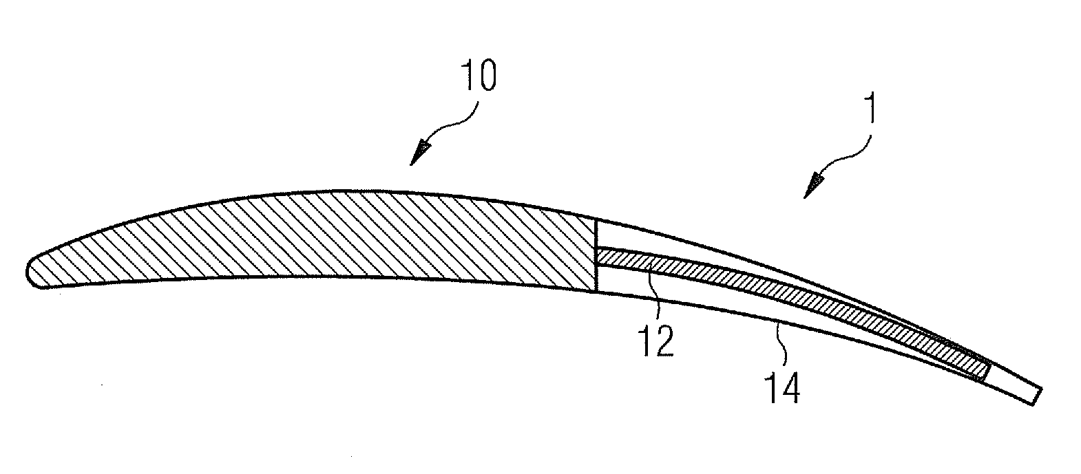
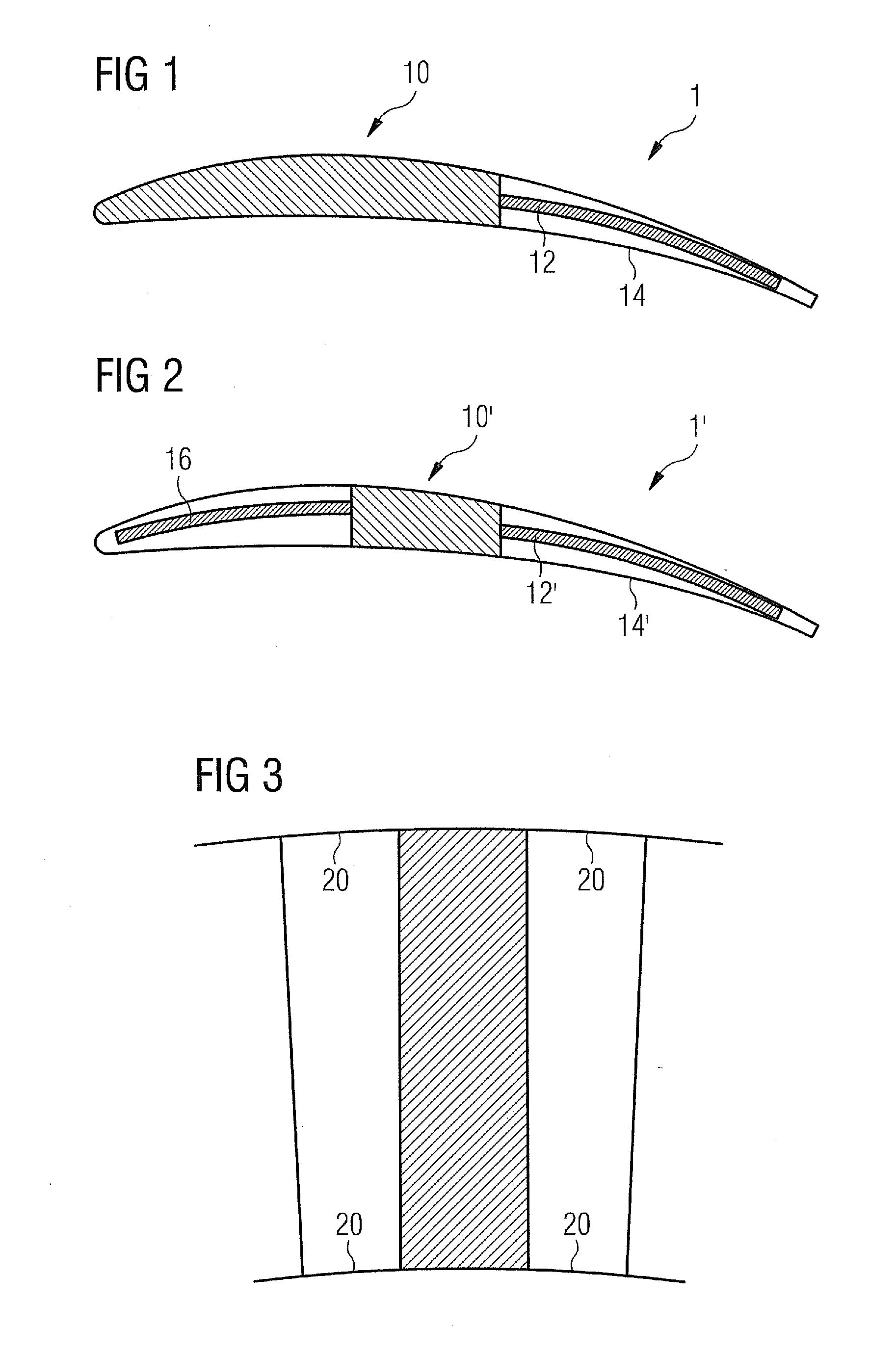
[0035]FIGS. 1 and 2 show a schematic longitudinal section of a first and the invention, which may be used in a compressor, for instance in the compressor of a turbocharger.

[0036]Inlet vane 1 comprises a rigid, structurally fixed portion 10 which is coupled to an aft portion that comprises an electroactive polymer (EAP) member 12 and a flexible skin 14 of metal or polymer materials. In the present embodiment, EAP member 12 is laminated to skin 14, and is supplied with voltage using electrical leads (not shown). The electrical leads can be led through the structural fixed portion 10. Alternatively, the structural fixed portion 10 itself can be electrically conductive so as to replace one or more of the leads. If it replaces more than one lead it would comprise a respective number of conductive portions which are electrically isolated against each other.

[0037]As the person skilled in the art will acknowledge, in the entire description and claims, fore and aft relate to the upstream edg...

fourth embodiment

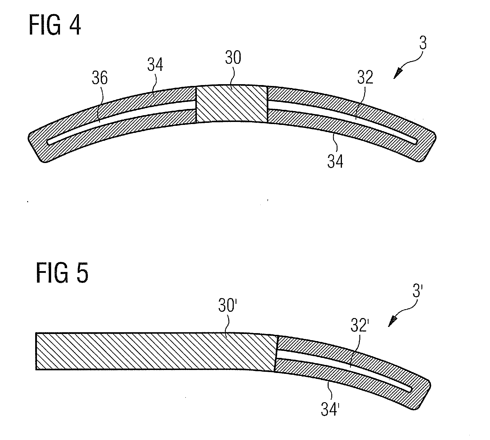
[0043]FIGS. 4 and 5 shows a schematic longitudinal section of a third and the invention, respectively, which may be used in a silencer of a turbocharger.

[0044]The configuration of these embodiments generally corresponds to the configuration of the embodiments described with respect to FIGS. 1 and 2. In particular, what has been said about supplying the EAPs with voltage with respect to the first and second embodiment is also true for the third and fourth embodiment.

[0045]In the silencer vane 3 shown in FIG. 4, a rigid portion 30 is located between and coupled to a fore portion that comprises an EAP layer 36 laminated to covering layer 34, and an aft portion, also comprising an EAP layer 32 laminated to covering layer 34.

[0046]Regarding the contact area between the EAP layers and covering layers of the third and fourth embodiment, the details given with regard to the first and second embodiment of the invention apply respectively.

[0047]In the silencer vane 3′ shown in FIG. 5, the rig...


PUM


Abstract

An inlet guide vane for a compressor is provided. The inlet guide vane is adjustable to modify gas flow properties in the compressor, wherein electroactive polymers are arranged in the inlet guide vane such that the shape of the inlet guide vane is adjusted in a specified manner upon applying a voltage to the inlet guide vane.

Description

CROSS REFERENCE TO RELATED APPLICATIONS[0001]This application is the US National Stage of International Application No. PCT / EP2009 / 050368, filed Jan. 14, 2009 and claims the benefit thereof. The International Application claims the benefits of European Patent Office application No. 08001433.5 EP filed Jan. 25, 2008. All of the applications are incorporated by reference herein in their entirety.FIELD OF INVENTION[0002]The invention relates to an inlet guide vane for a gas compressor, the vane being adjustable to modify gas flow properties in the compressor, as well as a compressor, turbocharger, and gas turbine therefor.BACKGROUND OF INVENTION[0003]In order to dynamically change the gas flow properties of the gas inlet of a compressor, it is known to use inlet guide vanes that can be turned so that the vanes are provided with a variable stagger or camber. U.S. Pat. No. 3,442,493 and U.S. Pat. No. 5,520,511 show vanes consisiting of two movable parts of fixed form.[0004]In such implem...

Claims


Application Information

Patent Timeline
Patent Type & Authority Applications(United States)
IPC IPC(8): F04D29/56
CPCF01D5/148F01D17/162F02C7/042F05D2300/505F04D29/462F04D29/664F04D27/0246F04D29/023F04D29/4213F04D29/563F05D2250/51F05D2300/43
Inventor NILSSON, ULF
Owner SIEMENS AG
Learn More