
Microbial power generation device

a power generation device and microorganism technology, applied in the direction of electrochemical generators, electrical apparatus, fuel cells, etc., can solve the problems of increasing the manufacturing cost of anodes, low actual energy conversion efficiency, and low power generation rate, so as to improve the power generation efficiency of microbial power generation

Inactive Publication Date: 2010-12-30
KURITA WATER INDUSTRIES LTD
View PDF4 Cites 6 Cited by
  • Summary
  • Abstract
  • Description
  • Claims
  • Application Information

AI Technical Summary

Benefits of technology

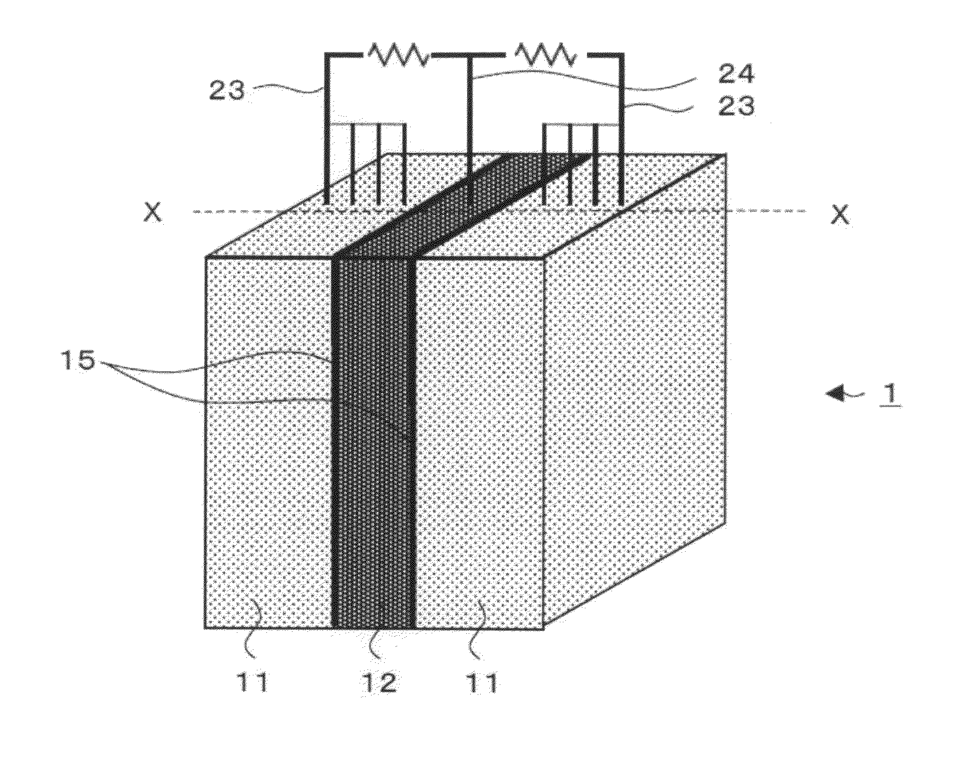
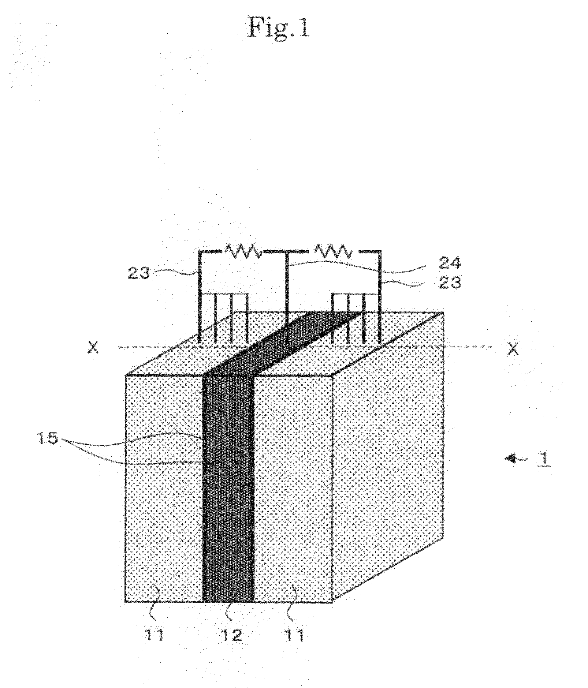
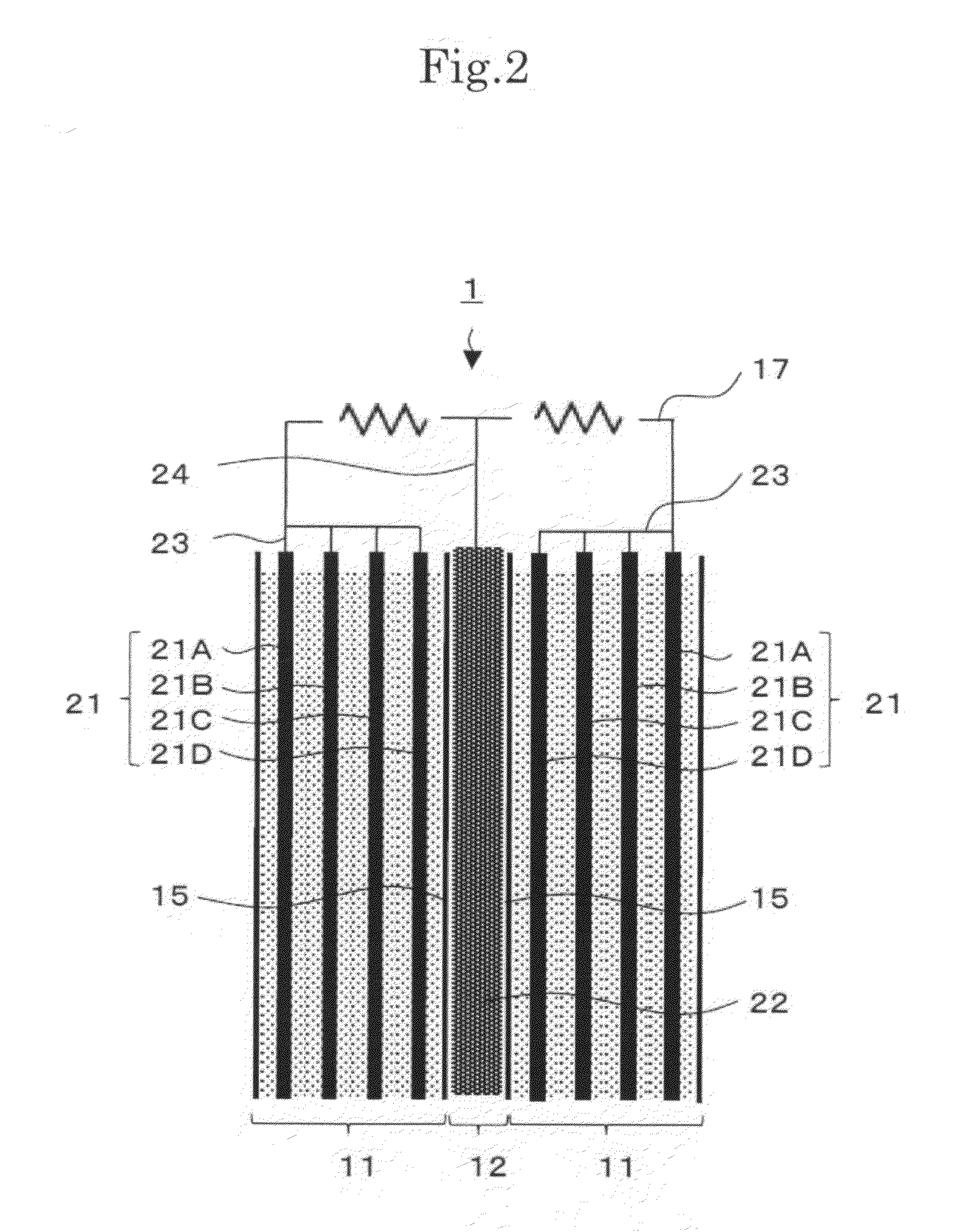
[0009]The inventors of the present invention discovered that preventing a short pass of influent within an anode chamber by allowing an electroconductive support material which maintains microbial growth to exist within the anode chamber contributes to an improvement in efficiency of microbial power generation. In addition, the inventors discovered that by adhering a nonconductive membrane which separates the anode chamber and a cathode chamber with electrodes arranged on each of the anode chamber and cathode chamber respectively, the movement of electrons and protons (H+) which are generated by a microbial reaction is accelerated and power generation efficiency is improved. Specifically, the present invention provides the following.
[0030]According to the present invention it is possible to improve the power generation efficiency of microbial power generation.

Problems solved by technology

However, the actual energy conversion efficiency is low and therefore improvements in power generation rates are required.
In addition, because an additional process which introduces a functional group to the anode is necessary the manufacturing costs of the anode increase.
In addition, adverse effects on the microbial reaction may be generated depending on the type of mediator.

Method used


Image

  • Microbial power generation device
  • Microbial power generation device
  • Microbial power generation device

Examples


examples

[0062]A microbial power generation device 2 shown in FIG. 4 was assembled as example 1. The power generation device 2 is comprised by inserting a anode first conductive support material 21 between two cathode second conductive support materials 22, and the total volume is 1050 mL, with the volume of the anode chamber 11 being 700 mL and each cathode chamber 12 being 175 mL. A circulation path 30 arranged with a circulation tank which circulates a discharge effluent from the anode chamber 11 is arranged on the power generation device 2, a pH adjustment means 31 which adjusts the pH of a solution which flows in the circulation path is arranged and the pH of the solution within the anode chamber 11 is maintained at 7 or more and 9 or less. An alkali injection device is used as the pH adjustment means 31.

[0063]The first conductive support material 21 is formed by sticking together four sheets of graphite felt (made by Toyo Carbon Co., Ltd) having a thickness of 1 cm with a conductive ad...

example 2

[0070]In example 2, a single sheet of graphite felt (3 mm thick) is used as the first conductive support material instead of the first conductive support material used in example 1. In addition to this, the size of the anode chamber 11 was changed to 52.5 mL and the graphite felt used as the first conductive support material was used so that the entire anode chamber was filled. Conditions other than these were the same as in example 1. When microbial power generation was carried out, the voltage generated was 305 mV and the current was 610 mA. At this time, the circuit resistance was 0.5Ω.


PUM

PropertyMeasurementUnit
thicknessaaaaaaaaaa
thicknessaaaaaaaaaa
concentrationaaaaaaaaaa

Abstract

A microbial power generation device includes an anode chamber which maintains a microbe and which is supplied with influent which includes an electron donor, a cathode chamber supplied with an electron acceptor, a nonconductive membrane having a first face and an opposing second face and arranged between the anode chamber and the cathode chamber, a first electro-conductive support material having a rough surface which has asperity spreading close to the first face of the nonconductive membrane, and formed by a porous material having approximately the same shape as the interior of the anode chamber, and arranged within the anode chamber, and a second electro-conductive support material having a rough surface which has asperity spreading close to the second face of the nonconductive membrane.

Description

CROSS-REFERENCE TO RELATED APPLICATIONS[0001]This is a continuing application, filed under 35 U.S.C. §111(a), of International Application PCT / JP2008 / 072385, filed Dec. 10, 2008, it being further noted that foreign priority benefit is based upon Japanese Patent Application 2007-329691, filed Dec. 21, 2007, the entire disclosures of which are incorporated herein by reference.BACKGROUND[0002]1. Field[0003]The present invention is related to a power generation device which uses a metabolic reaction of a microbe. In particular, the present invention is related to a microbial power generation device which extracts the reducing power obtained when a microbe decomposes an organic substrate by oxidation as electrical energy.[0004]2. Description of the Related Art[0005]In recent years, the requirements for a power generation method that takes into account the global environment are increasing and the technological development of microbial power generation is progressing. Microbial power gene...

Claims


Application Information

Patent Timeline
Patent Type & Authority Applications(United States)
IPC IPC(8): H01M8/16
CPCH01M8/0232H01M8/0234H01M8/0245H01M8/0271Y02E60/527H01M8/04194H01M8/16H01M8/248H01M8/0297Y02E60/50
Inventor FUKASE, TETSUROORITA, NOBUHIRO
Owner KURITA WATER INDUSTRIES LTD
Learn More