Eureka AIR delivers breakthrough ideas for toughest innovation challenges, trusted by R&D personnel around the world.

Catheter assembly

a catheter and assembly technology, applied in the field of catheters, can solve the problems of excessive thin wall, too weak guiding catheter to withstand kinking, and difficulty in presenting the transmission force to advance (or push) the catheter or the torque to rotate the catheter at the proximal side, and achieves sufficient strength, convenient and safe insertion, and flexible distal end

Inactive Publication Date: 2010-12-30
TERUMO KK
View PDF10 Cites 7 Cited by
  • Summary
  • Abstract
  • Description
  • Claims
  • Application Information

AI Technical Summary

Benefits of technology

[0016]It is an object of the present invention to provide a catheter assembly which has flexibility at the distal end as well as sufficient strength, permits safe and sure insertion to the desired position by simple operation, and accommodates a variety of procedure catheters by its enlarged inside diameter.
[0018]The catheter assembly has no possibility of damaging the vessel wall because it is inserted to the desired site in the blood vessel in such a way that the outer catheter and the inner catheter behave as one body and it permits the distal end (the second soft tip) of the inner catheter to slightly protrude from the distal open end of the outer catheter while ensuring good operability (pushability and torque transmission) and good kink resistance. It is to be noted that, it can be used in the same way as an ordinary catheter because of the very short distance between the distal end of the outer catheter and the distal end of the inner catheter. When the inner catheter is withdrawn after arrival at the desired site, the distal end of the outer catheter approximately coincides with the distal end of the catheter assembly. In addition, the distal end of the inner catheter is so flexible that the bent shape of the outer catheter remains unchanged. Thus the catheter assembly can be inserted to the desired site rapidly, surely, and safely.

Problems solved by technology

Therefore the transmitting force to advance (or push) the catheter or torque to rotate the catheter by manipulation at its proximal side is presented difficulties by buckling and / or bending of the catheter.
However, with an excessively thin wall to meet these requirements, the guiding catheter is too weak to withstand kinking when it is inserted in a meandering portion of the blood vessel.
Furthermore, a guiding catheter with an excessively thin wall has a sharp tip which might damage the blood vessel at the time of insertion.
Thus it is difficult to obtain an ideal guide catheter that meets the contradictory requirements mentioned above.

Method used


Image

  • Catheter assembly
  • Catheter assembly
  • Catheter assembly

Examples


Embodiment Construction

[0070]In what follows, the catheter assembly according to the present invention will be described in more detail with reference to the preferred embodiments illustrated in the accompanying drawings.

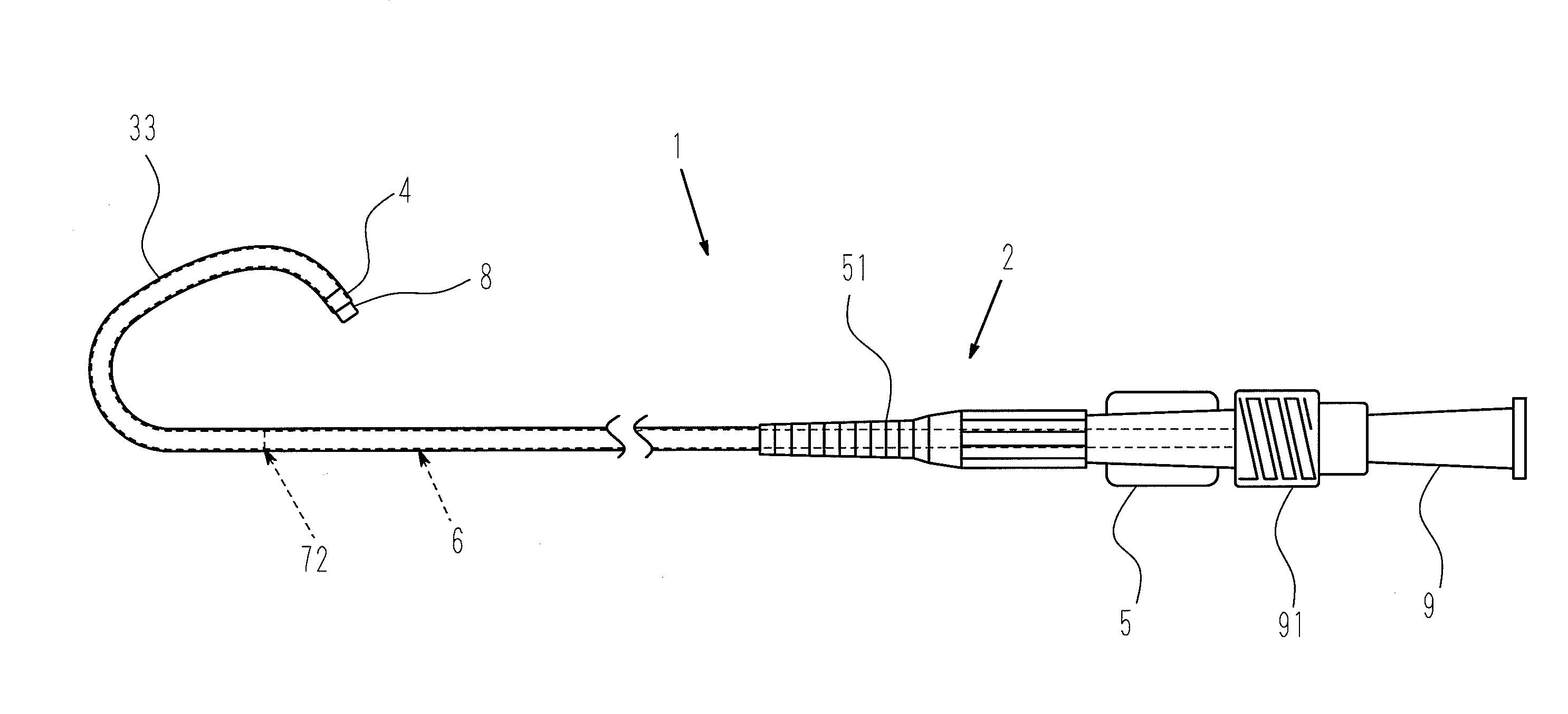
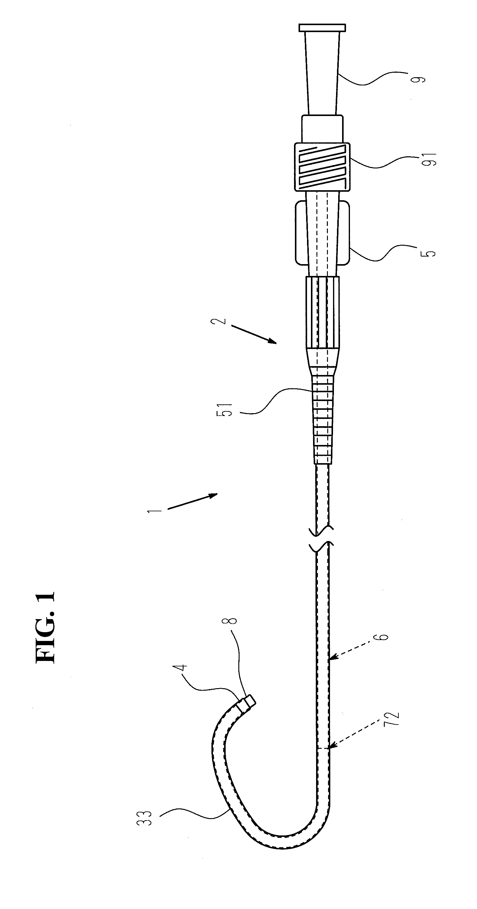
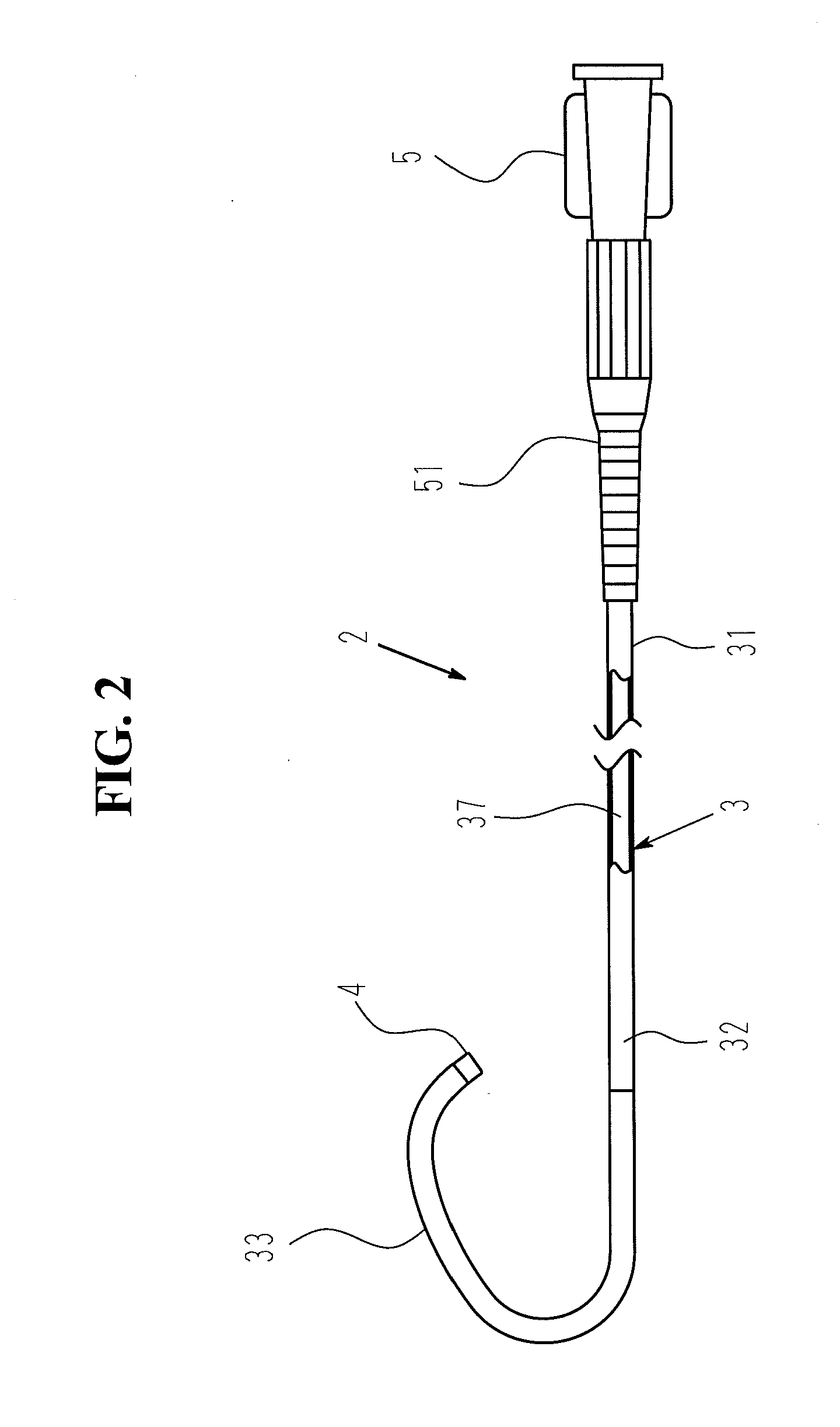
[0071]Incidentally, this specification uses the term “proximal” and “distal” to note respectively the right side and the left side in FIGS. 1 to 5. Moreover, this specification uses the term “near position” and “far position” to note respectively the side close to the proximal end and the side far from the proximal end.

[0072]The catheter assembly 1 shown in FIG. 1 is designed to be used as a guiding catheter to guide a procedure catheter to a target site or as an angiographic catheter to inject a contrast medium into a target site of a blood vessel. The procedure catheter such as a dilatation catheter (i.e. balloon catheter) or a catheter for stent transportation to a target site of a blood vessel is used to dilate a stenotic site in the coronary artery by the balloon or the stent.

[0073]T...


PUM

PropertyMeasurementUnit
distanceaaaaaaaaaa
wt %aaaaaaaaaa
diameter D1aaaaaaaaaa

Abstract

A catheter assembly (1), including an outer catheter (2) and an inner catheter (6) capable of being inserted into the outer catheter (2). The catheter assembly is characterized in that an outer catheter hub (5) and an inner catheter hub (9) are fixedly fitted to each other so that the two catheters are not rotated nor moved relative to each other, and when fitted to each other, at least a part of the tip of the inner catheter (6) is protruded by 10 mm or shorter from the tip of the outer catheter (2). When the inner catheter is inserted into the outer catheter, operabilities such as kink resistance, press-in performance, and torque transmission performance are excellent and the inner diameter thereof is increased when the catheter is used after indwelling. As a result, the range of choices of a catheter for treatment can be increased.

Description

[0001]This application is a continuation of application Ser. No. 10 / 582,914, filed Jun. 14, 2006, and claims priority under 35 U.S.C. §119 to Japanese Patent Application No. 2003-417064 filed Dec. 15, 2003.TECHNICAL FIELD[0002]The present invention relates to a catheter assembly to be used for introduction into the heart or the peripheral tissues, especially the left and right coronary arteries (coronary artery for short hereinafter). More particularly, the present invention relates to a guiding catheter to introduce a procedure catheter (e.g. a dilatation catheter for PTCA, a catheter for stent delivery or the like) to a target position of a blood vessel or also relates to a catheter to inject an angiographic medium into a target position of a blood vessel.BACKGROUND ART[0003]It is common practice to treat the stenosis in a blood vessel by means of a dilatation catheter (balloon catheter) or other procedure catheter. The former is designed such that the balloon inflates after inser...

Claims


Application Information

Patent Timeline
Patent Type & Authority Applications(United States)
IPC IPC(8): A61M25/14A61M25/09A61M25/00A61M25/088A61M29/02
CPCA61M25/0041A61M25/0053A61M25/104A61M2025/1079A61M2025/0081A61M2025/0681A61M2025/0046
Inventor ITOU, TAKENARIFUKUOKA, TETSUYA
Owner TERUMO KK
Why Eureka
Eureka Blog
Learn More