Arrangement at a supercharged internal combustion engine

Inactive Publication Date: 2011-01-06
SCANIA CV AB
View PDF2 Cites 13 Cited by
  • Summary
  • Abstract
  • Description
  • Claims
  • Application Information

AI Technical Summary

Benefits of technology

[0004]The object of the present invention is to provide an arrangement whereby a gaseous medium which contains water vapour

Problems solved by technology

If the coolant is also colder than 0° C., there is obvious risk of the water freezing to ice within the cooler.
The lower the temperature of the coolant in the low-temperature cooling system, the greate

Method used


Image

  • Arrangement at a supercharged internal combustion engine
  • Arrangement at a supercharged internal combustion engine

Examples


Embodiment Construction

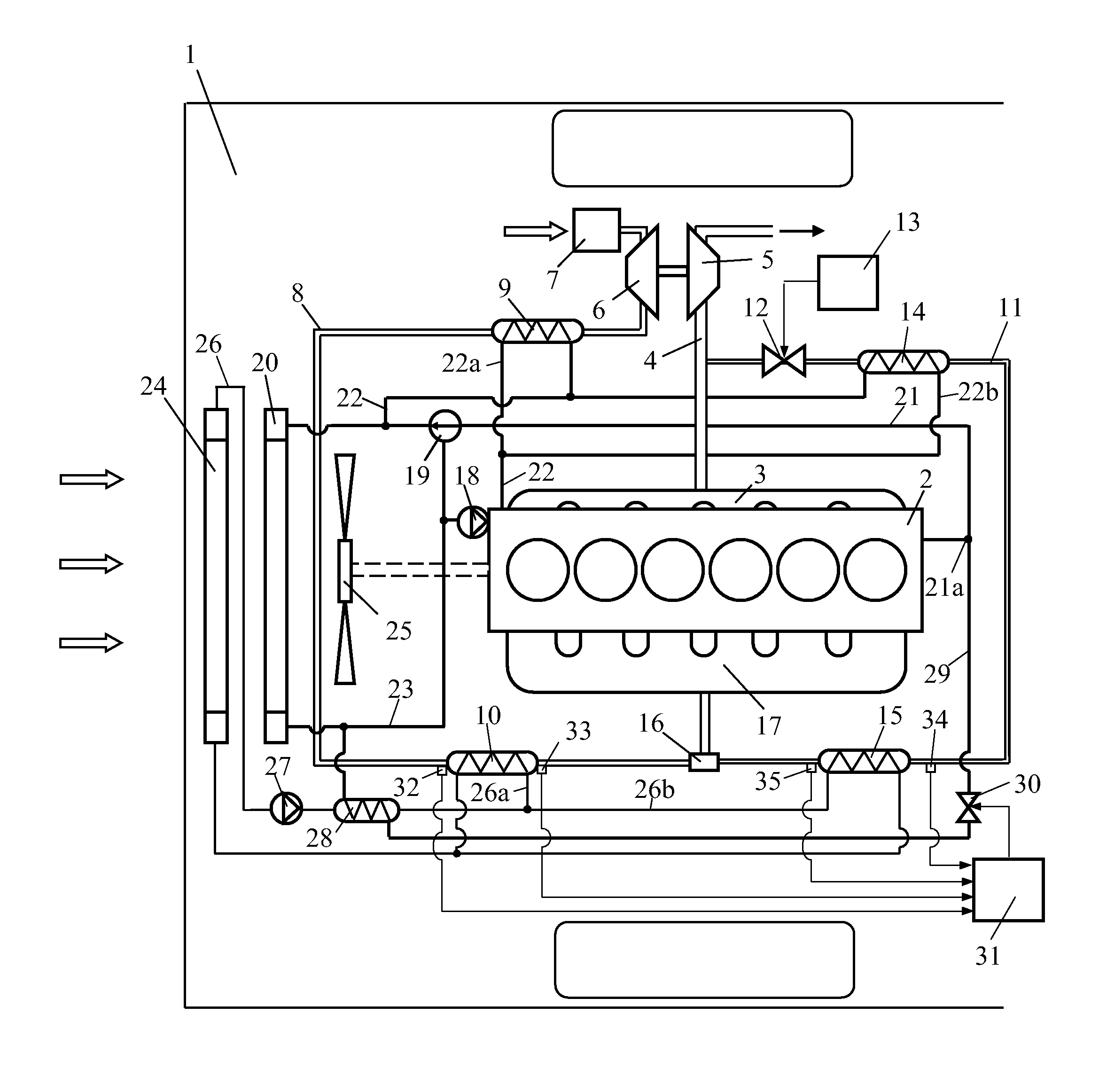
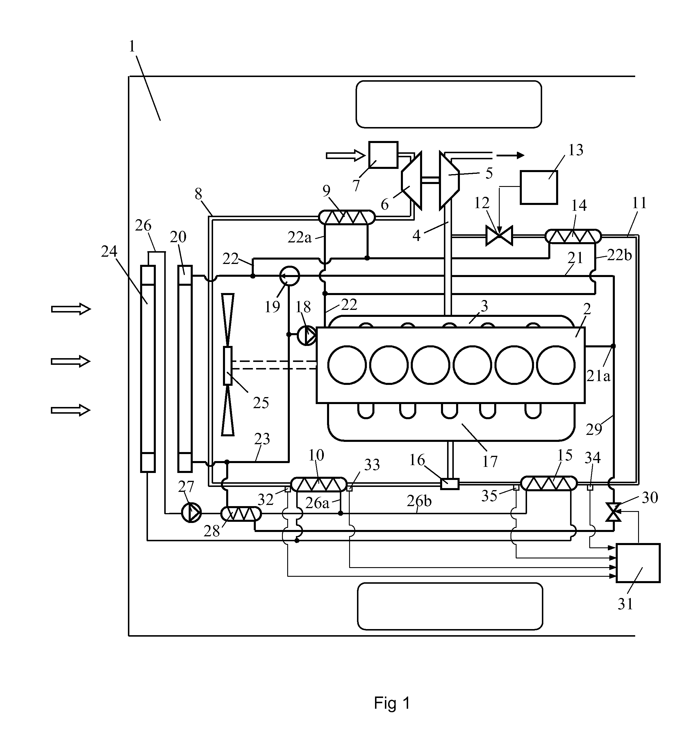
[0012]FIG. 1 depicts an arrangement for a supercharged combustion engine which is intended to power a schematically depicted vehicle 1. The combustion engine is here exemplified as a diesel engine 2. The diesel engine 2 may be intended to power a heavy vehicle 1. The exhaust gases from the cylinders of the diesel engine 2 are led via an exhaust manifold 3 to an exhaust line 4. The diesel engine 2 is provided with a turbo unit which comprises a turbine 5 and a compressor 6. The exhaust gases in the exhaust line 4, which are at above atmospheric pressure, are led initially to the turbine 5. The turbine 5 is thus provided with driving power which is transferred, via a connection, to the compressor 6. The compressor 6 uses this power to compress air which is drawn into an air inlet line 8 via an air filter 7. The air in the inlet line is cooled initially in a first coolant-cooled charge air cooler 9. The air is cooled in the first charge air cooler 9 by coolant from the combustion engin...


PUM


Abstract

An arrangement for a supercharged combustion engine for preventing ice formation in a cooler. A first cooling system with a circulating coolant. A second cooling system with a circulating coolant which during normal operation of the combustion engine is at a lower temperature than the coolant in the first cooling system. The cooler in which a gaseous medium for the engine and which contains water vapour is intended to be cooled by the coolant in the second cooling system. A heat exchanger. A valve which can be placed in a first position wherein coolant from at least one of the cooling systems is prevented from flowing through the heat exchanger and in a second position wherein coolant from both of the cooling systems flows through the heat exchanger so that the coolant in the second cooling system is warmed by the coolant in the first cooling system.

Description

BACKGROUND TO THE INVENTION, AND STATE OF THE ART[0001]The present invention relates to an arrangement for a supercharged combustion engine according to the preamble of claim 1.[0002]The amount of air which can be supplied to a supercharged combustion engine depends on the pressure of the air but also on the temperature of the air. Supplying the largest possible amount of air to the combustion engine entails effective cooling of the air before it is led to the combustion engine. The air is usually cooled in a charge air cooler arranged at a front portion of a vehicle. At that location the charge air cooler has a cooling air flow at the temperature of the surroundings flowing through it, which makes it possible for the compressed air to be cooled to a temperature close to the temperature of the surroundings. In cold weather conditions, the compressed air may be cooled to a temperature below the dewpoint temperature of the air, resulting in precipitation of water vapour in liquid form...

Claims


Application Information

Patent Timeline
IPC IPC(8): F01P7/00
CPCF01P7/165F01P2003/187F01P2005/105Y02T10/121F02B29/0412F02M25/0706F01P2060/02F02M26/04F02B29/0443F02B29/0493F02M26/24F02M26/28F02M26/33
Inventor KARDOS, ZOLTANSODERBERG, ERIK
Owner SCANIA CV AB
Why Eureka
Try Eureka