
Electric rotating tool, control method, and program

a technology of electric rotating tools and control methods, applied in the direction of manufacturing tools, portable power-driven tools, instruments, etc., can solve the problems of increasing the manufacturing cost increasing the total weight increasing the overall length of electric rotating tools or the outer periphery of the tip-tool side. , to achieve the effect of reducing the usability or operability of electric rotating tools, accurate detection of tightening torque, and increasing total weigh

Inactive Publication Date: 2011-01-06
HITACHI KOKI CO LTD
View PDF6 Cites 59 Cited by
  • Summary
  • Abstract
  • Description
  • Claims
  • Application Information

AI Technical Summary

Benefits of technology

[0005]In the electric rotating tool, when the torque measurement means is provided on the rotation output shaft of the drive mechanism part, the tightening torque can be accurately detected. However, in the torque measurement means, a mechanism part of the drive output shaft included therein is large; therefore, the overall length of the electric rotating tool or the outer periphery of the tip-tool side is inevitably increased, and the total weight is increased. When the size and the weight of the electric rotating tool are increased, the usability or operability of the electric rotating tool is lowered. Moreover, since a special torque detector and a detection circuit device are required in order to detect torque, manufacturing cost of the electric rotating tool is also increased.
[0006]The present invention has been accomplished in order to solve the problems of the above described conventional technique, and an object of the present invention is to provide an electric rotating tool, control method, and program capable of appropriately managing tightening torque by a simple means.
[0055]According to above described further another configuration of the present invention, the current, which flows through the stator coil, and the number of rotations of the rotor are controlled by adjusting the PWM duty of the PWM signal; therefore, the tightening torque can be readily controlled. Particularly, the present invention is suitable for an electric rotating tool in which a brushless DC motor capable of controlling a wide range of rotation speed by varying the PWM duty is used as a drive power source.
[0056]Furthermore, according to the above described present invention, the motor can be driven by the tightening torque that is within the range which does not cause burnout of the motor; therefore, power consumption of the battery pack due to interruption of operations can be reduced.
[0057]Moreover, according to the above described invention, torque management is carried out by the tightening torque in accordance with the load state or the PWM duty of the PWM signal; therefore, efficiency of the workload per one time of charge of the battery pack can be improved.

Problems solved by technology

However, in the torque measurement means, a mechanism part of the drive output shaft included therein is large; therefore, the overall length of the electric rotating tool or the outer periphery of the tip-tool side is inevitably increased, and the total weight is increased.
Moreover, since a special torque detector and a detection circuit device are required in order to detect torque, manufacturing cost of the electric rotating tool is also increased.

Method used


Image

  • Electric rotating tool, control method, and program
  • Electric rotating tool, control method, and program
  • Electric rotating tool, control method, and program

Examples


Embodiment Construction

[0066]Hereinafter, an embodiment of the present invention will be explained in detail based on drawings. Note that, in all the drawings for explaining the embodiment, the members having the same functions are denoted by the same reference numerals, and repetitive explanations thereof will be omitted.

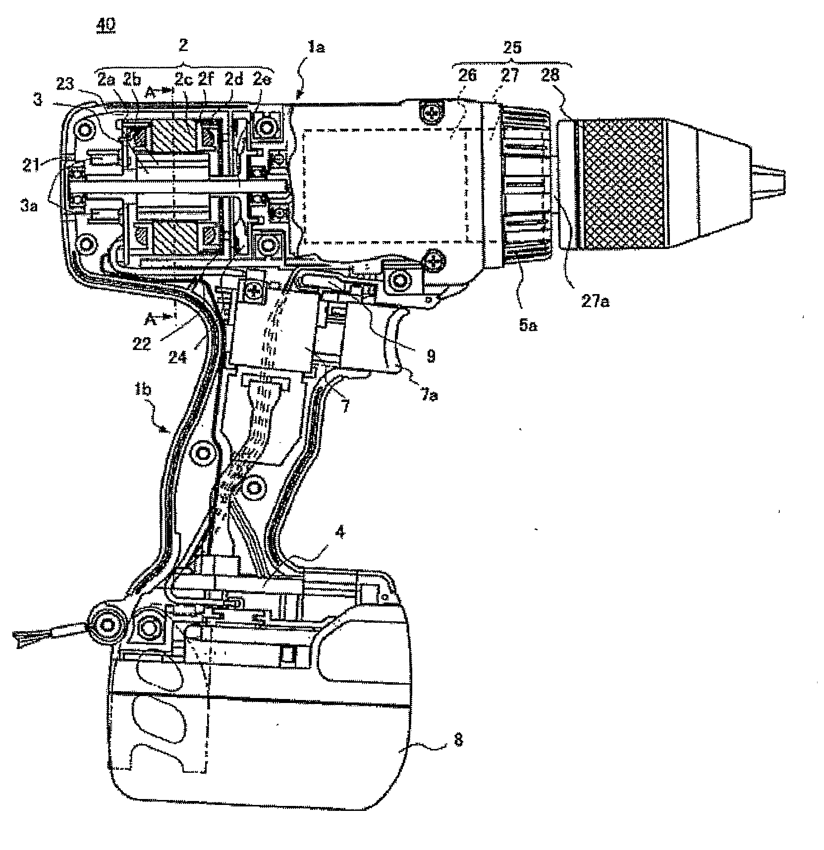
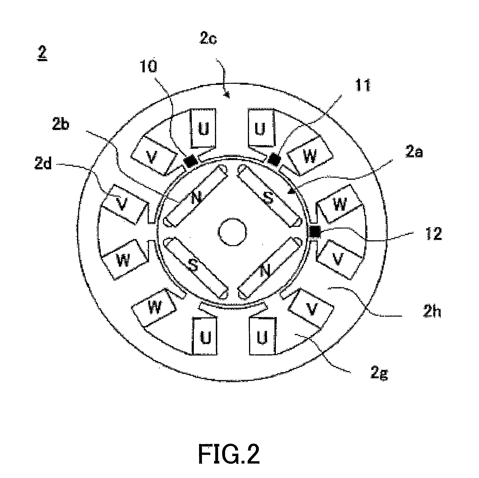
[0067]FIG. 1 is an overall structure drawing of a cordless-type driver drill according to an embodiment of the present invention. FIG. 2 is a cross-sectional drawing of a motor of the driver drill along a line A-A shown in FIG. 1. Furthermore, FIG. 3 is a functional block diagram showing the entirety of the driver drill shown in FIG. 1.

[0068][Assembly Configuration of Electric Rotating Tool]

[0069]As shown in FIG. 1, a motor 2 is housed in a body housing part 1a of the driver drill 40. A tip tool such as a driver or a drill (not shown) is connected to the motor 2 via a power transmission part 25. The power transmission part 25 transmits the driving force of the motor 2 to the tip tool suc...


PUM


Abstract

Tightening torque is appropriately managed by a simple means. An electric rotating tool (40) has a brushless DC motor (2), an inverter circuit part (3), and a control circuit part (4). The control circuit part (4) has a current detecting circuit (18), which detects a motor current I, a rotation number detecting circuit (17), which detects the number of rotations of the motor (N), and a computing part (19), which calculates first tightening torque (T1) based on the detection information of the motor current (I) and calculates second tightening torque (T2) based on the number of rotations of the motor (N). The computing part (19) estimates tightening torque Tave based on the estimate value of the first tightening torque (T1) or the second tightening torque (T2). The computing part (19) stops driving the motor (2) when the estimated tightening torque Tave exceeds a set value Tset.

Description

TECHNICAL FIELD[0001]The present invention relates to an electric rotating tool which requires setting of tightening torque such as a driver, an impact driver, or a driver drill which carries out screw tightening of a bolt, a nut, etc. and, in particular, to the electric rotating tool having torque detection techniques for detecting the tightening torque which is transmitted from an output shaft of a drive source such as an electric motor to a tip tool.BACKGROUND ART[0002]Conventionally, in a tightening operation of a fastener such as a bolt, nut, or screw, an electric rotating tool such as an impact driver or a driver drill is used. In the electric rotating tool, in order to appropriately adjust tightening torque that is transmitted from an electric motor to a tip tool such as a driver bit and required for screw tightening, when the fastening torque at the tip tool exceeds a set value, operation of a drive source including the electric motor is stopped, or transmission of the power...

Claims


Application Information

Patent Timeline
IPC IPC(8): B25B23/147B25F5/00H02P29/02B25B21/00B25B23/14
CPCB25B21/00H02P29/028B25B23/147H02P29/032
Inventor IWATA, KAZUTAKA
Owner HITACHI KOKI CO LTD
Features
  • Generate Ideas
  • Intellectual Property
  • Life Sciences
  • Materials
  • Tech Scout
  • Unparalleled Data Quality
  • Higher Quality Content
  • 60% Fewer Hallucinations
Learn More