
Landing gear legs and method of making

Inactive Publication Date: 2011-01-06
CORDY JR CLFFORD B
View PDF21 Cites 2 Cited by
  • Summary
  • Abstract
  • Description
  • Claims
  • Application Information

AI Technical Summary

Benefits of technology

[0009]The problem of heavy landing gear is solved by making the gear legs of a composite structure containing two or more fiber materials that have different physical properties from one another. One fiber material, or group of fiber materials, uses fibers with high yield strength and low modulus of elasticity, said fibers running essentially parallel to the axis of the gear leg. These are built into a structure that is much stronger than the present steel gear legs used on airplanes of similar weight. In this case, “stronger” means that it will not break or suffer permanent deformation in an impact that would leave the steel landing gear seriously bent, permanently.
[0010]The second fiber material, or group of materials, have moderate to high yield strength and high modulus of elasticity. These are incorporated into the composite at angles far from the axis of the gear leg. These provide the torsional rigidity needed to suppress the tendency of the wheel and its fairing to flutter at high airplane speeds.
[0011]Since multiple materials can be incorporated into a composite structure, it is possible to construct landing gear legs of multiple materials in such a way that landing impact energy is stored in a strong, flexible fiber while at the same time a strong, stiff fiber provides rigidity that eliminates flutter. Consider the two requirements in more detail.
[0014]Rotational stiffness is maximized by using a fiber with a high modulus of elasticity, not necessarily exceptionally strong. This fiber is formed into a tube, ideally with a circular cross section. The fibers are laid into the surface at large angles to the axis of the tube. In flutter, the initial driving force is typically small, and it increases as the magnitude of the oscillation increases, until something is destroyed. If the part in question is sufficiently stiff to prevent flutter, it does not have to be very strong. Thus, modulus of elasticity is the primary consideration for these fibers.
[0016]As the experienced gear leg designer works with the concepts presented herein, he or she will recognize there is an added degree of freedom available with this design. This allows an optimization unavailable with gear legs constructed of a single material, or of a composite containing only a single fiber material. In addition to light weight, it is desirable that the gear leg be thin in the vertical direction, to minimize air drag in flight. However, using a minimum weight of a soft (I) fiber in a thin gear leg will produce a leg that is very flexible. It is likely that it would be so flexible that it would be uncomfortable to land and taxi, and it is also more prone to flutter in high speed flight. A thicker gear leg can be made lighter and stiffer, in both vertical springiness and torsion, but drag increases. A stiffer (I) fiber will also make a stiffer gear leg, with no increase in drag, but with an increase in weight. A stiffer (I) fiber also allows the (T) fiber to be laminated at an angle further from 90 degrees, which makes the (T) lamination more efficient (better torsional stiffness per unit weight).
[0023]In terms of eliminating the possibility of damaging the (T) fibers, they could be laid at 90 degrees to the axis of the gear leg. However, this would not give the desired torsional rigidity. To achieve torsional rigidity, there must be a web of fibers crossing each other, as shown in FIG. 2. To maximize the torsional strength and rigidity, it is desirable to lay the (T) fibers at an angle only slightly further from zero (in the + and − directions) than that given in the formula above.

Problems solved by technology

Pilots are known to make spectacularly bad landings.
In general, dissipation elements are large, heavy, and not aerodynamic.
Steel is very heavy, but it is cheap, it is stiff, and it will store more energy per unit weight than most other materials.
Furthermore, if the plane is landed so hard that the elastic limit of the steel is exceeded, the steel will generally bend a long way before it breaks.
But many of them are very stiff (have a high modulus of elasticity).
Furthermore, when their elastic limits are exceeded, most composites will snap, not bend.
The reason this “obvious” solution is not used is that it causes another problem.
However, landing gear must be stiff.
If it is not stiff enough, the wheel, and wheel fairing, will flutter at high flight speeds.
This will likely destroy the airplane.

Method used


Image

  • Landing gear legs and method of making
  • Landing gear legs and method of making
  • Landing gear legs and method of making

Examples


Embodiment Construction

[0032]In general, the main gear takes the brunt of the impact in a bad landing. Consequently, the drawings and description included here are primarily directed toward the main gear. However, pilots also manage to make colossal impacts with nose and tail wheels, and all descriptions herein are obviously usable in those applications too.

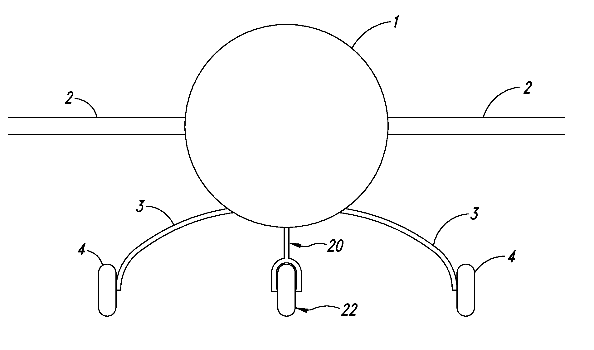
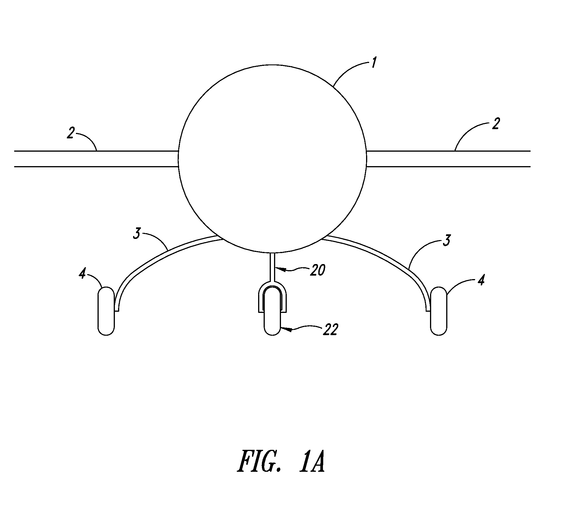
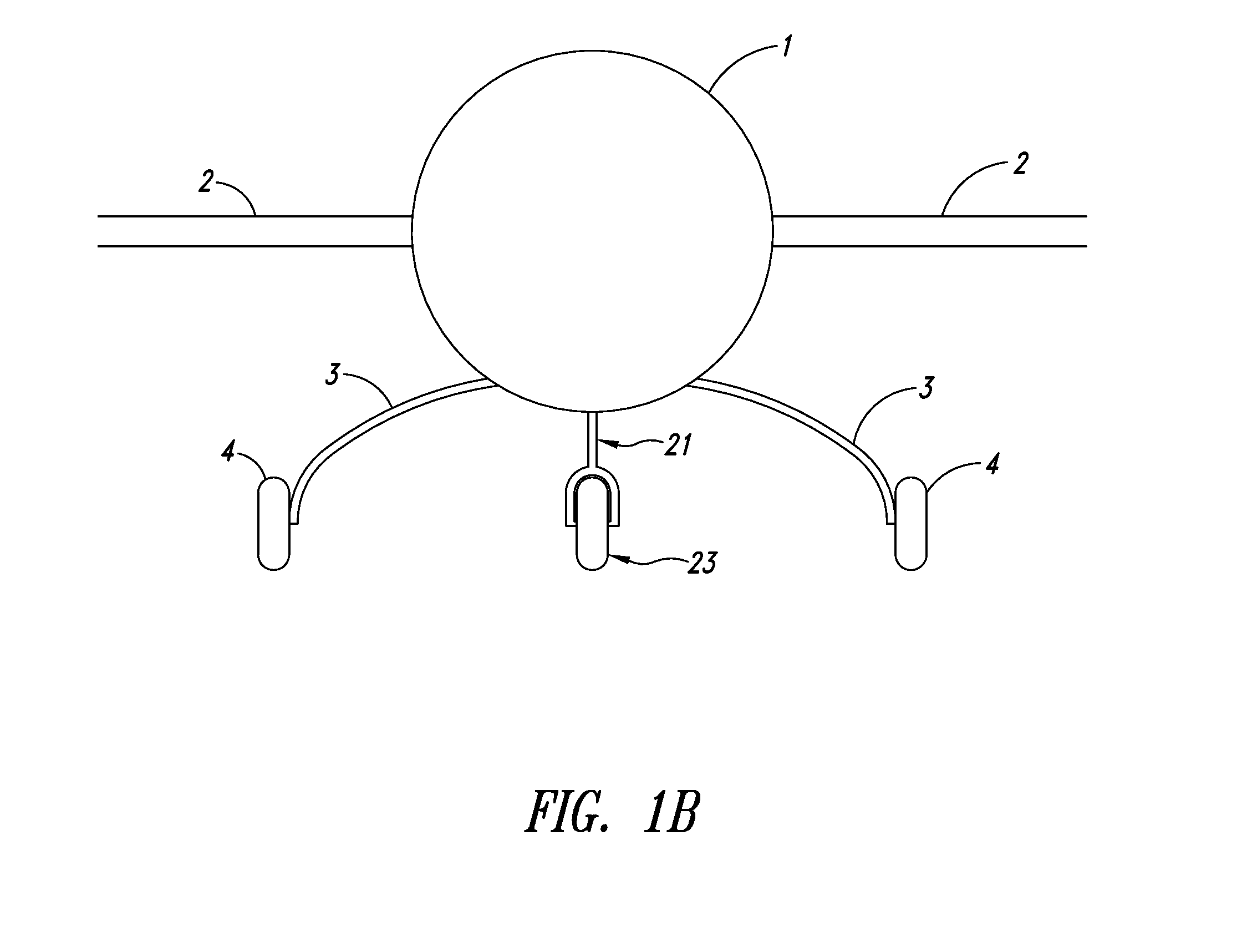
[0033]The front view of a generic airplane is shown in FIGS. 1A-1B, with fuselage (1) and wings (2) sitting on gear legs (3). In FIG. 1A, gear legs (3) are rigidly attached to fuselage (1) and to the axles (not shown) of wheel assemblies (4). It is common that gear legs (3) are individual units, each rigidly attached into the structure of fuselage (1). It is also common that gear legs (3) form a single beam between both wheel assemblies (4), with fuselage (1) perched in the middle of said beam. It is also common that gear legs (3) are firmly anchored into the structure of wings (2) rather than fuselage (1). It is also common that gear legs (3) are retr...


PUM


Abstract

An airplane gear leg that is strong, stiff, and capable of storing large amounts of energy and formed of a composite material that has first and second fiber materials. The first fiber material is very strong and flexible, allowing it to store a great deal of energy in a hard landing, and its fibers are oriented essentially parallel to the axis of the gear leg. The second fiber material is very stiff, providing the torsional rigidity necessary to avoid flutter, and its stiff fibers are laid at a large angle relative to the axis of the gear leg so their elastic limit is not exceeded during a hard landing.

Description

BACKGROUND[0001]1. Field of the Invention[0002]The present disclosure pertains to landing gear legs formed of composite material.[0003]2. Description of the Related Art[0004]Pilots are known to make spectacularly bad landings. The landing gear of the airplane is expected to survive such landings. To do so, the landing gear must be extremely strong and somewhat flexible. The airplane has some predetermined gross weight. There is some rate of descent when contact (impact) is made with an unyielding surface (runway). The maximum kinetic energy associated with a given rate of descent is:E=mV2 / 2[0005]where m is the maximum allowed gross mass of the airplane and V is the maximum rate of descent at impact that must be survived. Of course, a consistent set of units must be used. This is the energy the landing gear must be capable of storing and dissipating. In general, dissipation elements are large, heavy, and not aerodynamic. Thus, in most cases, essentially the entire impact energy must ...

Claims


Application Information

Patent Timeline
IPC IPC(8): B64C25/34B64C25/02
CPCB64C25/06
Inventor CORDY, JR., CLFFORD B.
Owner CORDY JR CLFFORD B
Learn More