Electromagnetic relay for starters

a technology of electric relay and starter, which is applied in the direction of relays, riveted connections, contacts, etc., can solve the problems of product cost rise and increase in the number of manufacturing processes, and achieve the effect of simplifying the manufacturing process

Active Publication Date: 2011-01-06
DENSO CORP
View PDF4 Cites 20 Cited by
  • Summary
  • Abstract
  • Description
  • Claims
  • Application Information

AI Technical Summary

Benefits of technology

[0011]The present invention has been made in order to solve the issues described above, and has as its object to provide an electromagnetic relay that is not necessary to use a large-scale production facility in order to provide a plurality of projection parts on a surface of a fixed contact that faces a movable contact, and enables a simplification of the manufacturing process.
[0017]According to the above-mentioned composition, since the first and second terminal-bolts and the fixed contact are assembled and fixed mechanically, joining processes, such as welding, are unnecessary. Thereby, the manufacturing process can be greatly simplified.
[0018]Because the plurality of concavo-convex parts provided in one surface of the fixed contact are at least partly curved, and have the same height, and project in a height direction from the fixed contact, loose connection of the movable contact and the fixed contacts can be prevented, since the tips of the concavo-convex parts can contact the surface of the movable contact when the movable contact contacts the fixed contact.

Problems solved by technology

However, in order to provided a plurality of projection parts in the point-of-contact side of the fixed contact as shown in U.S. Pat. No. 5,424,700, forging must be performed, thus a large-scale cold forge machine is needed, which becomes a factor in which product cost rises.
When forming the terminal-bolts and the fixed contact with different kinds of metals, welding etc is required to join the both; there will be a problem that number of manufacturing process may increase sharply.

Method used


Image

  • Electromagnetic relay for starters
  • Electromagnetic relay for starters
  • Electromagnetic relay for starters

Examples


first embodiment

[0035]In this first embodiment, an example of an electromagnetic relay applied to a switch for motor energization equipped in a starter is explained.

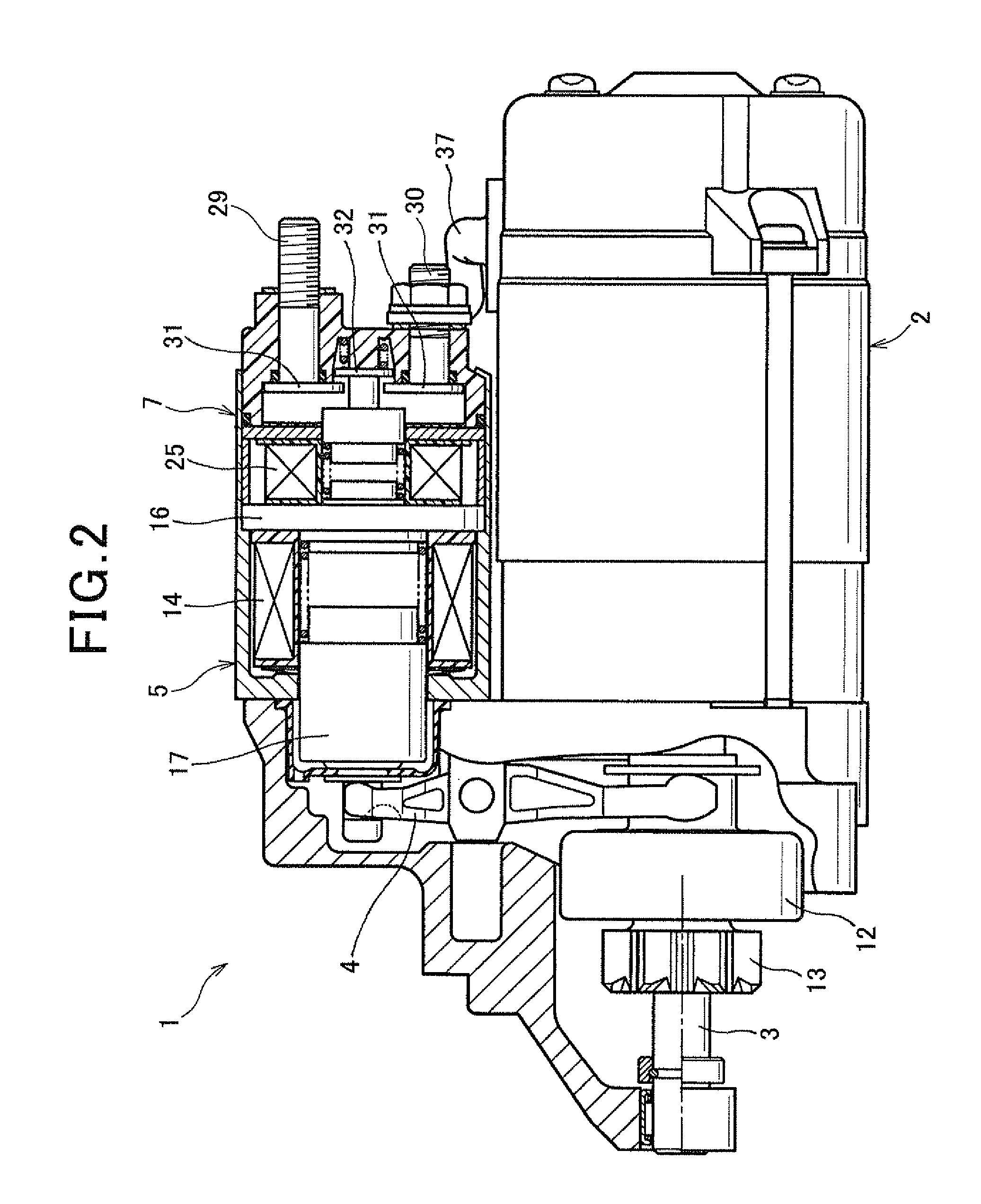
[0036]As shown in FIG. 2, the starter 1 has a motor 2, an output shaft 3, a pinion movable body (mentioned later), shift lever 4, a solenoid 5 for pushing out a pinion, a battery 6 (refer to FIG. 6), and a switch 7 for motor energization.

[0037]The motor 2 generates torque, and this torque is transmitted to the output shaft 3 to make it rotate. The pinion movable body is movably provided in an axial direction on a perimeter of the output shaft 3. The solenoid 5 pushes out the pinion movable body in an anti-motor direction (to the left of FIG. 2) via the shift lever 4. The switch 7 opens and closes a motor point-of-contact (explained later) provided in a motor circuit for passing current to the motor 2 from the battery 6 (referring to FIG. 6).

[0038]As shown in FIG. 6, the motor 2 is a commutator motor provided with a magnetic field 8 cons...

second embodiment

[0117]This second embodiment is an example showing the electromagnetic relay of the present invention applied to a common electromagnetic switch 42 for starters shown in FIG. 7.

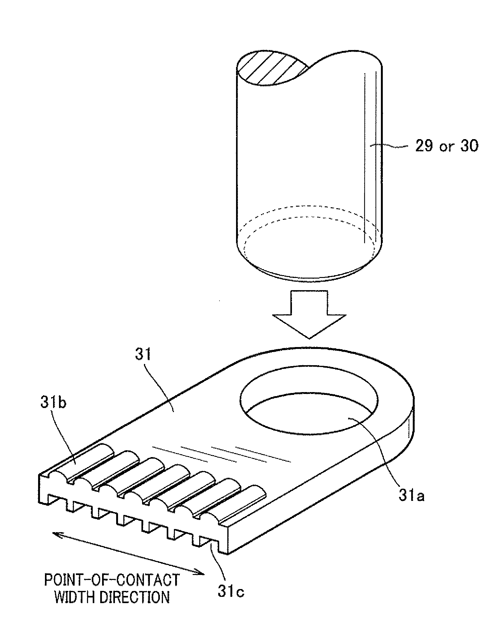
[0118]As shown in FIG. 7, the electromagnetic switch 42 has a set of fixed contacts 31 provided to two terminal-bolts 29 and 30, and a movable contact 32 that faces and movable to the set of these fixed contacts 31. The movable contact 32 is supported via an insulator 45 at an end of a rod 44 fixed to a plunger 43.

[0119]When a fixed iron core 16 is magnetized by the energization to an electromagnetic coil 46, the plunger 43 is attracted to the fixed iron core 16 pushing and contracting a return spring 47 arranged between the fixed iron cores 16 and the plunger 43.

[0120]By the movement of the plunger 43, a pinion movable body is pushed out in the axial direction via a gearshift connected to a joint 18, and the movable contact 32 contacts to the set of fixed contacts 31, thus a motor point-of-contact closes.

[01...

third embodiment

[0126]As shown in FIG. 8, the third embodiment is an example of the well-known plunger type relay 48, and an operation method is the same with the switch 7 for motor energization disclosed in the first embodiment.

[0127]That is, a relay 48 of the present embodiment has a relay coil 49 that generates a magnetic field by energization, a fixed iron core 16 magnetized by the energization to the relay coil 49, and a plunger 50 movable in an axial direction of the relay coil 49 facing the fixed iron core 16.

[0128]When the plunger 50 is attracted to the fixed iron core 16 by the attractive force of an electromagnet, the movable contact is energized by a contact pressure spring 40, and contacts a set of fixed contacts 31.

[0129]In this relay 48, the ends of the terminal-bolts 29 and 30 are press fit (or serration press fit) into fixed holes formed in the fixed contact 31 like the first embodiment, thus both are assembled electrically and mechanically.

[0130]A plurality of concavo-convex parts ...


PUM


Abstract

Terminal-bolts and a fixed contact are formed with different kinds of metals, and fixed to a fixing hole formed in the fixed contact by press fitting one end of the terminal-bolts. A plurality of concavo-convex parts is provided on a surface of the fixed contact that faces the movable contact. A plurality of concavo-convex portions is provided on another surface of the fixed contact that faces an anti movable-contact side. The concavo-convex portions are arranged so that positions of concave parts of the concavo-convex portions match positions of convex parts of the concavo-convex portions provided in the opposite surface of the fixed contact. The concavo-convex parts are at least partly curved, and have the same height and project in a height direction from the fixed contact.

Description

CROSS-REFERENCE TO RELATED APPLICATION[0001]This application is based on and claims the benefit of priority from earlier Japanese Patent Applications No. 2009-156752 filed on Jul. 1, 2009, and No. 2009-282891 filed on Dec. 14, 2009, the descriptions of which are incorporated herein by reference.BACKGROUND OF THE INVENTION[0002]1. Technical Field of the Invention[0003]The present invention relates to an electromagnetic relay for starters that opens and closes an electric point-of-contact using the attractive force of an electromagnet.[0004]2. Description of the Related Art[0005]Conventionally, an electromagnetic switch for starters using an electromagnetic relay is known as disclosed in U.S. Pat. No. 5,424,700, for example[0006]The electromagnetic switch disclosed in U.S. Pat. No. 5,424,700 has an operation that opens and closes the main point-of-contact provided in a motor circuit of a starter.[0007]This electromagnetic switch has a B terminal-bolt that is connected to a power suppl...

Claims


Application Information

Patent Timeline
IPC IPC(8): H01H1/00
CPCH01H1/06H01R4/06H01H51/065H01H50/14
Inventor USAMI, SHINJINIIMI, MASAMIMURATA, MITSUHIROSAITOH, MIKIO
Owner DENSO CORP
Why Eureka
Try Eureka