Optical fibre circuit monitoring system and monitoring device included in this system

Active Publication Date: 2011-01-06
SUMITOMO ELECTRIC IND LTD
View PDF2 Cites 37 Cited by
  • Summary
  • Abstract
  • Description
  • Claims
  • Application Information

AI Technical Summary

Benefits of technology

[0016]The object of the present invention is to provide a remote fiber test system and test eq

Problems solved by technology

Particularly, in a subscriber optical communication system, the point of the trouble must quickly be detected and restored when a trouble such as breakage or increase of the transmission loss occurs in an optical fiber line or optical network unit.
However, if the power of the probe light is increased

Method used


Image

  • Optical fibre circuit monitoring system and monitoring device included in this system
  • Optical fibre circuit monitoring system and monitoring device included in this system
  • Optical fibre circuit monitoring system and monitoring device included in this system

Examples


embodiment 1

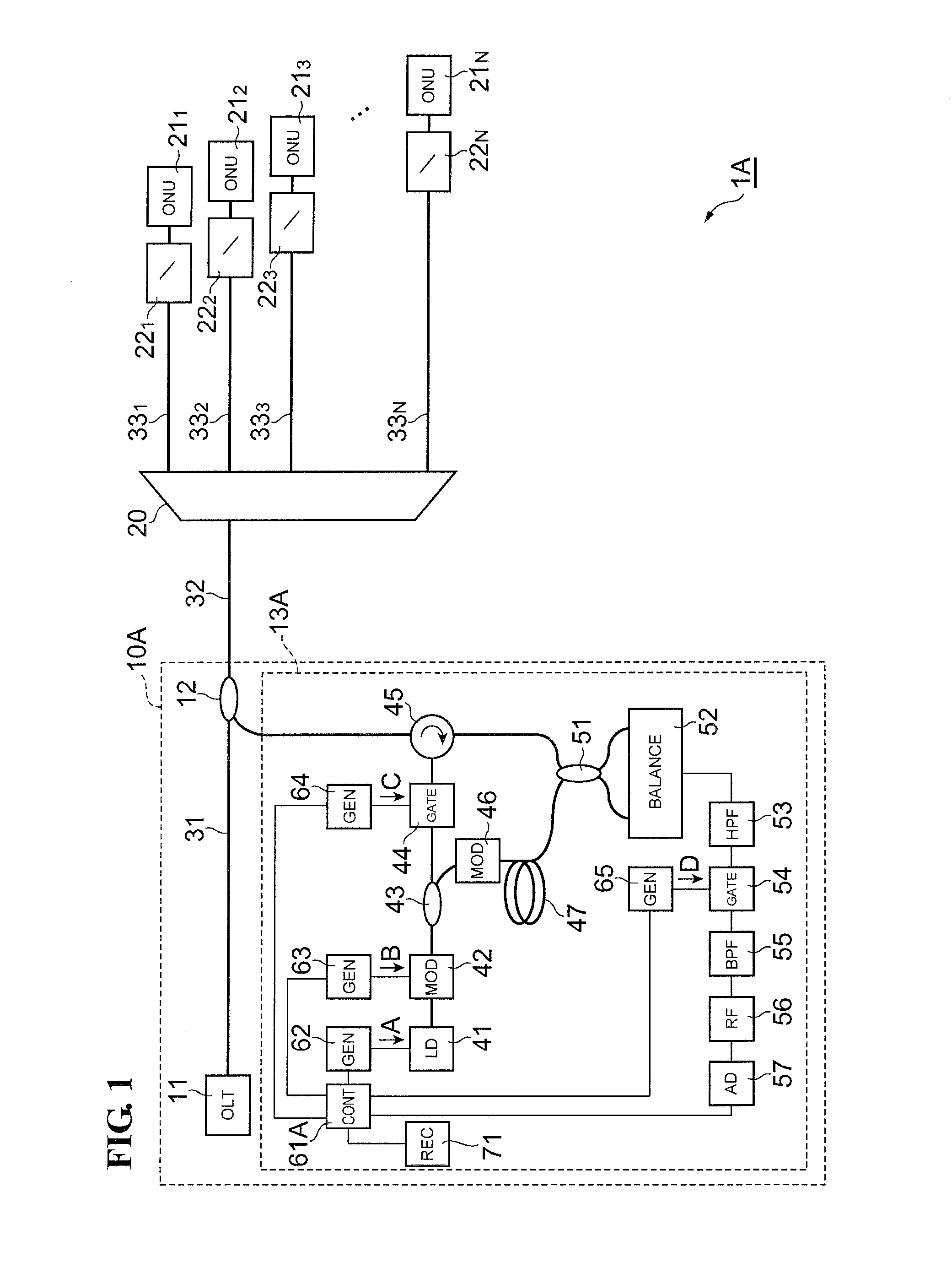
[0036]FIG. 1 is a conceptional schematic diagram showing a remote fiber test system 1A equipped with optical fiber line test equipment 13A relating to Embodiment 1 of the present invention. The remote fiber test system 1A, in which an optical line terminal (OLT) 11 provided in a central office 10A and N-number of optical network units (ONU) 211 to 21N are optically connected mutually through an optical splitter 20 and optical fiber lines, is used for making optical communication between the optical line terminal 11 and each optical network unit 21n. Here, N is an integer that is equal to or more than 2, and n is each integer that is one or more and N or less. The configuration of the remote fiber test system 1A is called Passive Optical Network (PON). Typically, the branching number N is 4 to 32.

[0037]The central office 10A is equipped with a multiplexer 12 and optical fiber line test equipment 13A, in addition to the optical line terminal 11. The optical line terminal 11 and the mu...

embodiment 2

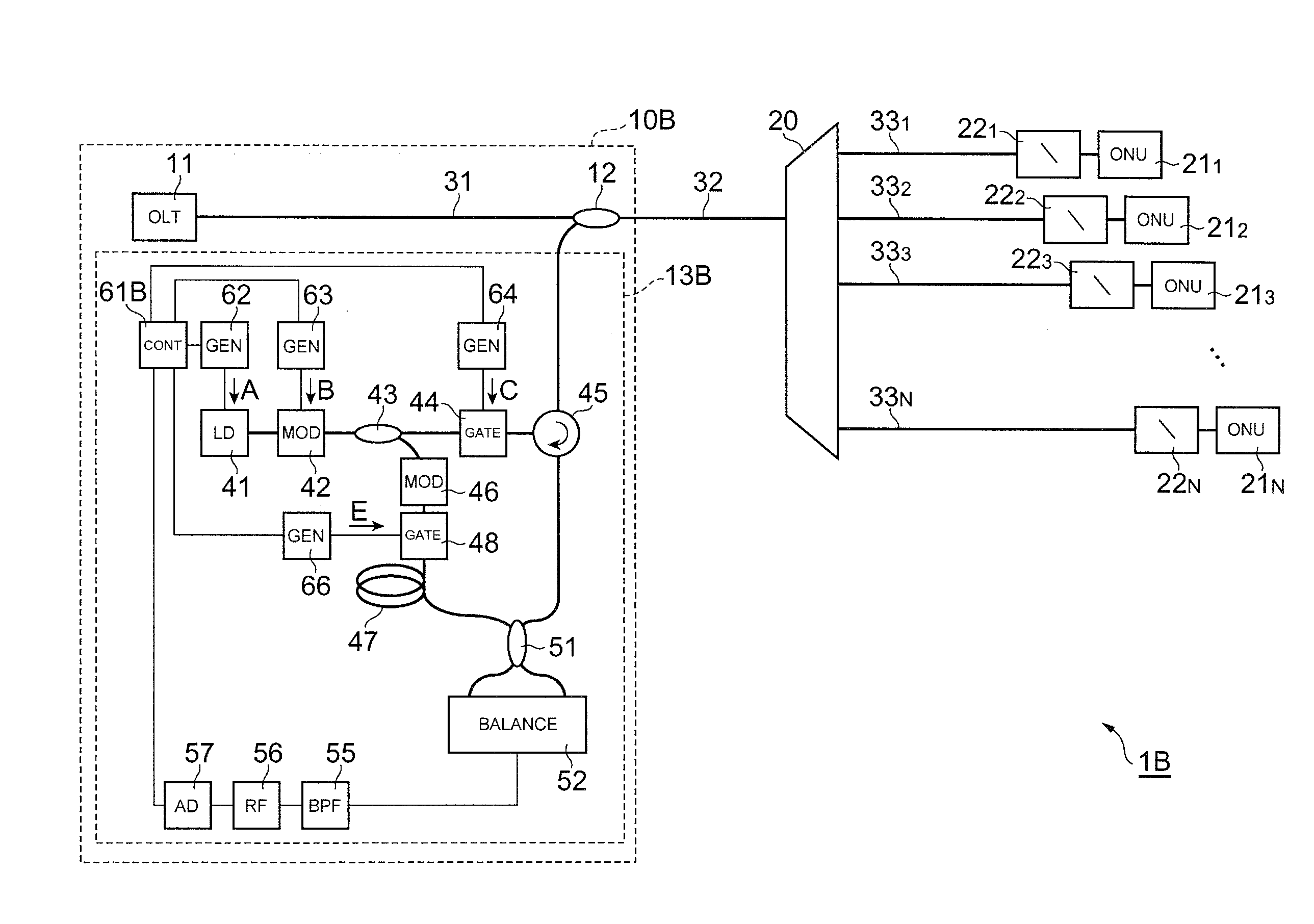
[0075]FIG. 6 is a conceptional schematic diagram showing a remote fiber test system 1B equipped with optical fiber line test equipment 13B relating to Embodiment 2 of the present invention. The remote fiber test system 1B differs from the remote fiber test system 1A in that the remote fiber test system 1B is not equipped with the first filter 53, the electric signal gate 54, and the signal generator 65, and that it is equipped with a reference light gate 48, a signal generator 66, and a control unit 61B instead of the control unit 61A.

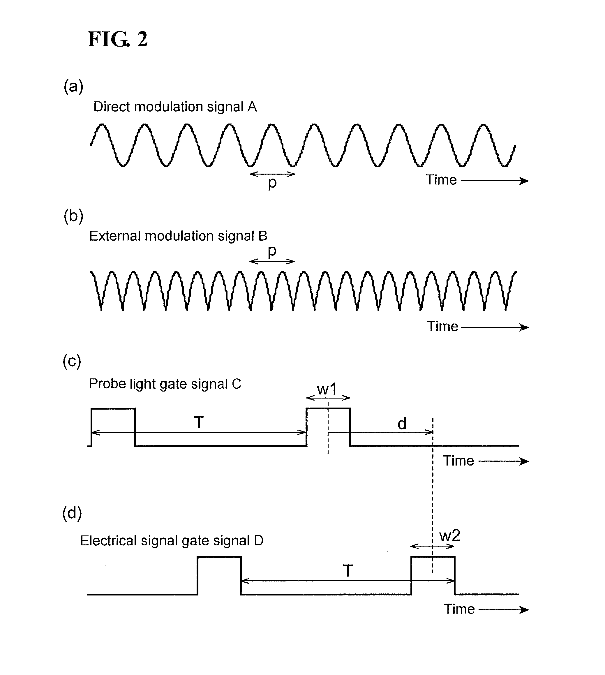
[0076]The reference light gate 48 is provided on the optical path of the reference light between the optical coupler 43 and the combiner 51. The reference light gate 48 receives the reference light output from the optical coupler 43, and also receives the reference light gate signal E output from the signal generator 66. The reference light gate signal E is similar to the electrical signal gate signal D of Embodiment 1, and is a periodic signal that ha...


PUM


Abstract

Optical fiber lines of a PON system can be monitored with the remote fiber test system having a practical structure, comprising a branch-type optical fiber line constituting the PON system and test equipment connected to the branch-type optical fiber line on the central office side. The test equipment comprises a light source, an optical splitter, a detecting part, and a control unit. The light source outputs light having an optical coherence function of a comb shape that is formed as a result of the optical frequency being modulated by a modulation signal of period p. The optical splitter receives light output from the light source and splits the light into probe light and reference light. The detecting part detects interference light that occurs from mutual interference between the reference light and reflected light arising while the probe light propagates through the branch-type optical fiber line. And, upon detection of the interference light, the detecting part converts the interference light into an electrical signal. The control unit changes the period p, and on the basis of the period p and the electrical signal output from the detecting part, obtains reflectance distribution along the direction of the probe light propagation in the branch-type optical fiber line.

Description

TECHNICAL FIELD[0001]The present invention relates to a remote fiber test system for monitoring an optical fiber line by using a reflectometry technique and to test equipment contained in the system.BACKGROUND ART[0002]In an optical communication system, it is important to detect a trouble such as a damage of an optical fiber line or an increase in the transmission loss. Particularly, in a subscriber optical communication system, the point of the trouble must quickly be detected and restored when a trouble such as breakage or increase of the transmission loss occurs in an optical fiber line or optical network unit. The use of so-called Passive Optical Network (PON) system has recently been spreading in the subscriber optical communication system. In the PON system, the connection between a central office and subscribers are made using a first optical fiber line extending from the central office, optical splitters, and a plurality of branched second optical fiber lines. This helps to...

Claims


Application Information

Patent Timeline
IPC IPC(8): G01N21/00G01M11/00H04B10/07H04B10/071H04B10/077H04B10/272
CPCH04B10/071G01M11/3172
Inventor HASEGAWA, TAKEMI
Owner SUMITOMO ELECTRIC IND LTD
Why Eureka
Try Eureka