Digital image compression by resolution-adaptive macroblock coding

a macroblock coding and resolution adaptation technology, applied in the field of digital imaging, can solve the problems of high data rate, burden on the transmission and storage of high definition video, and the need for significant bandwidth for storage and transmission, so as to achieve the effect of saving bandwidth, reducing bandwidth, and reducing bandwidth

Inactive Publication Date: 2011-01-06
MOTOROLA MOBILITY LLC +1
View PDF12 Cites 20 Cited by
  • Summary
  • Abstract
  • Description
  • Claims
  • Application Information

AI Technical Summary

Benefits of technology

This technique of altering the coding resolution saves bandwidth for those macroblocks whose contents are “easily” predicted (e.g., where a macroblock only contains low-frequency information), while stil...

Problems solved by technology

Such an extensive use of HD video requires a significant amount of bandwidth for storage and transmissi...

Method used


Image

  • Digital image compression by resolution-adaptive macroblock coding
  • Digital image compression by resolution-adaptive macroblock coding
  • Digital image compression by resolution-adaptive macroblock coding

Examples


first embodiment

According to the present invention (herein called “RAMB” for Resolution-Adaptive Macroblock coding), macroblocks that contain smoothly varying intensity values can be predicted in a lower-resolution grid by first low-pass filtering and then downsampling the input macroblock. (Here, “downsampling” or “decimating” means representing an original signal with fewer spatial samples. This is achieved by discarding some of the pixels of the original image based on a new sampling grid. Downsampling corresponds to a resolution reduction in the original image.) Because there are fewer residual values to encode in the lower-resolution representation (only 25% of the original resolution residual samples in a downsampling-by-two scenario), a substantial compression efficiency is achieved. In order to decode and display the macroblock in the original resolution, it is “upsampled” by interpolation. (Upsampling, the reverse of downsampling, means representing a low-resolution image in a high-resolut...

second embodiment

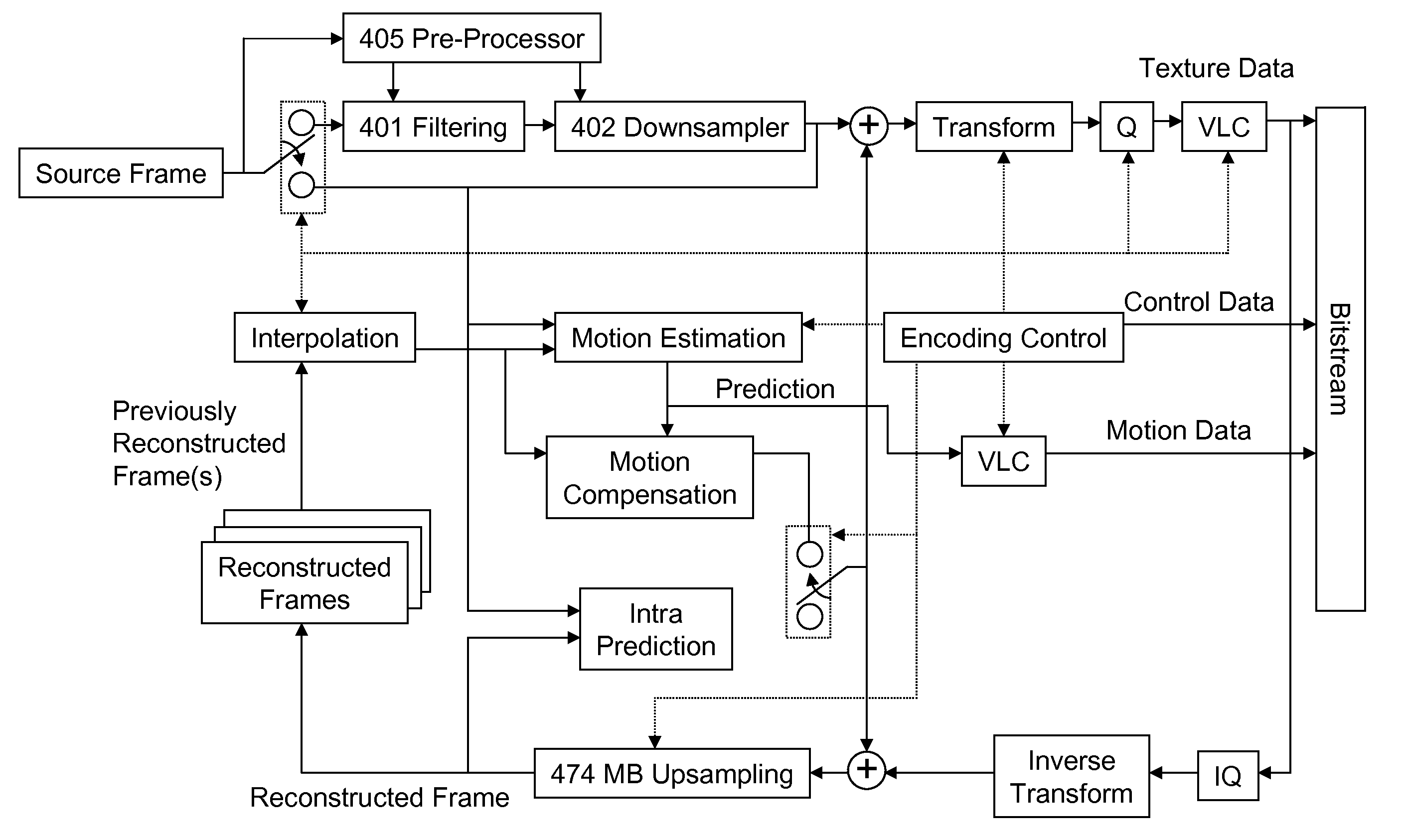
According to the present invention (herein called “MAHIRVCS” for Macroblock Adaptive Hierarchical Intermediate Resolution Video Coding System), at the encoder residuals are selectively downsampled, the residual data are reorganized, and the best encoding methodology in a rate-distortion framework is chosen. On the decoder, each decoded macroblock is analyzed, the residual data are reorganized, the optimal method for upsampling the residual data is determined, and the residual data are selectively upsampled.

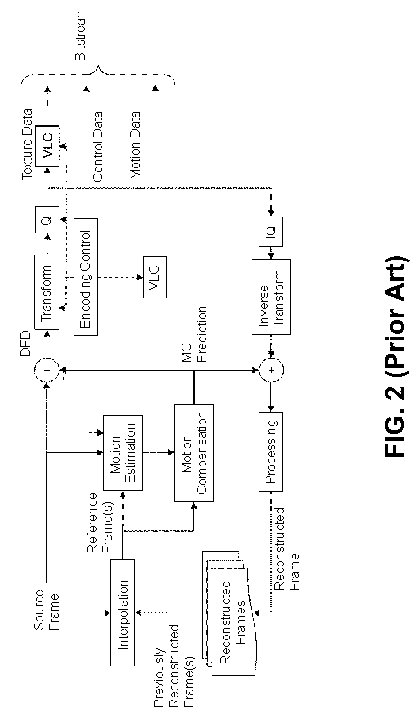
In some embodiments of MAHIRVCS, a few specific processing elements are added to the structure of an existing codec. FIG. 13 shows how MAHIRVCS-specific processing elements can be added to an existing encoder framework. (Compare FIG. 13 with the prior-art encoder of FIG. 2). Similarly, FIG. 14 shows the incorporation of MAHIRVCS-specific elements into an existing decoder. (Compare FIG. 14 with the prior-art decoder of FIG. 3).

The flowchart of FIGS. 15a and 15b presents one embodim...


PUM


Abstract

Disclosed is an image encoder that divides a digital image into a set of “macroblocks.” If appropriate, a macroblock is “downsampled” to a lower resolution. The lower-resolution macroblock is then encoded by applying spatial (and possibly temporal) prediction. The “residual” of the macroblock is calculated as the difference between the predicted and actual contents of the macroblock. The low-resolution residual is then either transmitted to an image decoder or stored for later use. In some embodiments, the encoder calculates the rate-distortion costs of encoding the original-resolution macroblock and the lower-resolution macroblock and then only encodes the lower-resolution macroblock if its cost is lower. When a decoder receives a lower-resolution residual, it recovers the lower-resolution macroblock using standard prediction techniques. Then, the macroblock is “upsampled” to its original resolution by interpolating the values left out by the encoder. The macroblocks are then joined to form the original digital image.

Description

FIELD OF THE INVENTIONThe present invention is related generally to digital imaging and, more particularly, to compressing digital images.BACKGROUND OF THE INVENTIONAs the availability of high definition (HD) video continues to increase, it will dominate the video market in the upcoming decades. Such an extensive use of HD video requires a significant amount of bandwidth for storage and transmission. For example, an HD spatial resolution of 1920×1080 progressive scan (1080p) results in approximately three Gigabits of uncompressed data per second of content. This enormous data rate gives rise to unprecedented visual quality which is well suited for liquid-crystal displays and plasma displays. On the other hand, high data rates place a burden on the transmission and storage of high definition video. For a typical example, a standard DVD-5 can only hold about twelve seconds of such content. This example highlights the need for exceptional compression systems for dealing with HD video. ...

Claims


Application Information

Patent Timeline
IPC IPC(8): H04N7/26
CPCH04N19/176H04N19/147H04N19/46H04N19/61H04N19/59H04N19/182H04N19/19H04N19/33H04N19/132
Inventor USLUBAS, SERHANKATSAGGELOS, AGGELOS K.ISHTIAQ, FAISALHSIANG, SHIH-TAMAANI, EHSAN
Owner MOTOROLA MOBILITY LLC
Why Eureka
Try Eureka