
Microtitre plate

a technology of microtitre plates and microtitre plates, which is applied in the field of microtitre plates, can solve the problems of false signals, high production costs, and the risk of coating the bottom surface of the well, and achieve the effect of low production costs and easy manufacturing processes

Inactive Publication Date: 2011-01-06
QIAGEN INSTR
View PDF3 Cites 3 Cited by
  • Summary
  • Abstract
  • Description
  • Claims
  • Application Information

AI Technical Summary

Benefits of technology

It is an objective of the present invention to provide a microtitre plate construction that facilitates real-time measurements and exhibits reduced optical cross-talk. The manufacturing cost of the microtitre plate should be low enough to make it disposable.
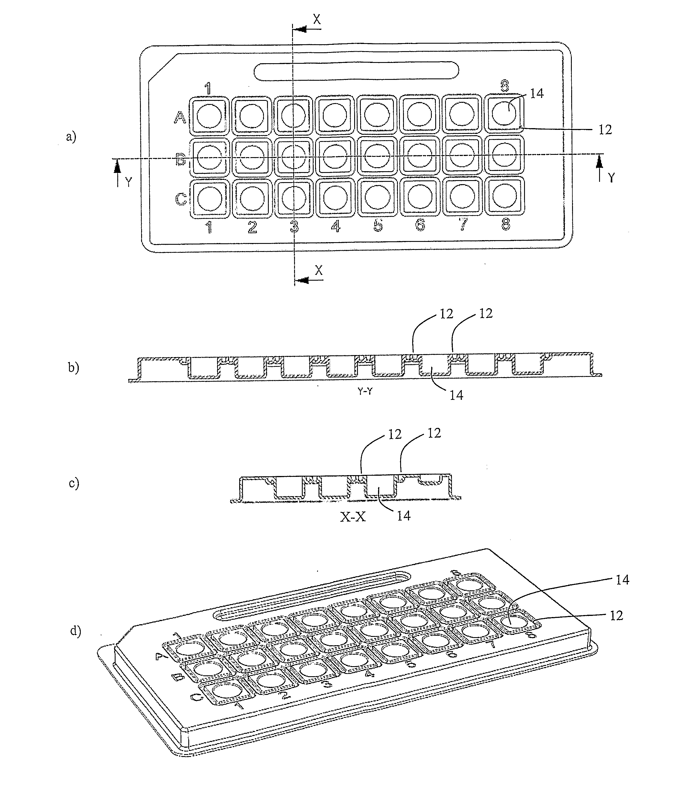
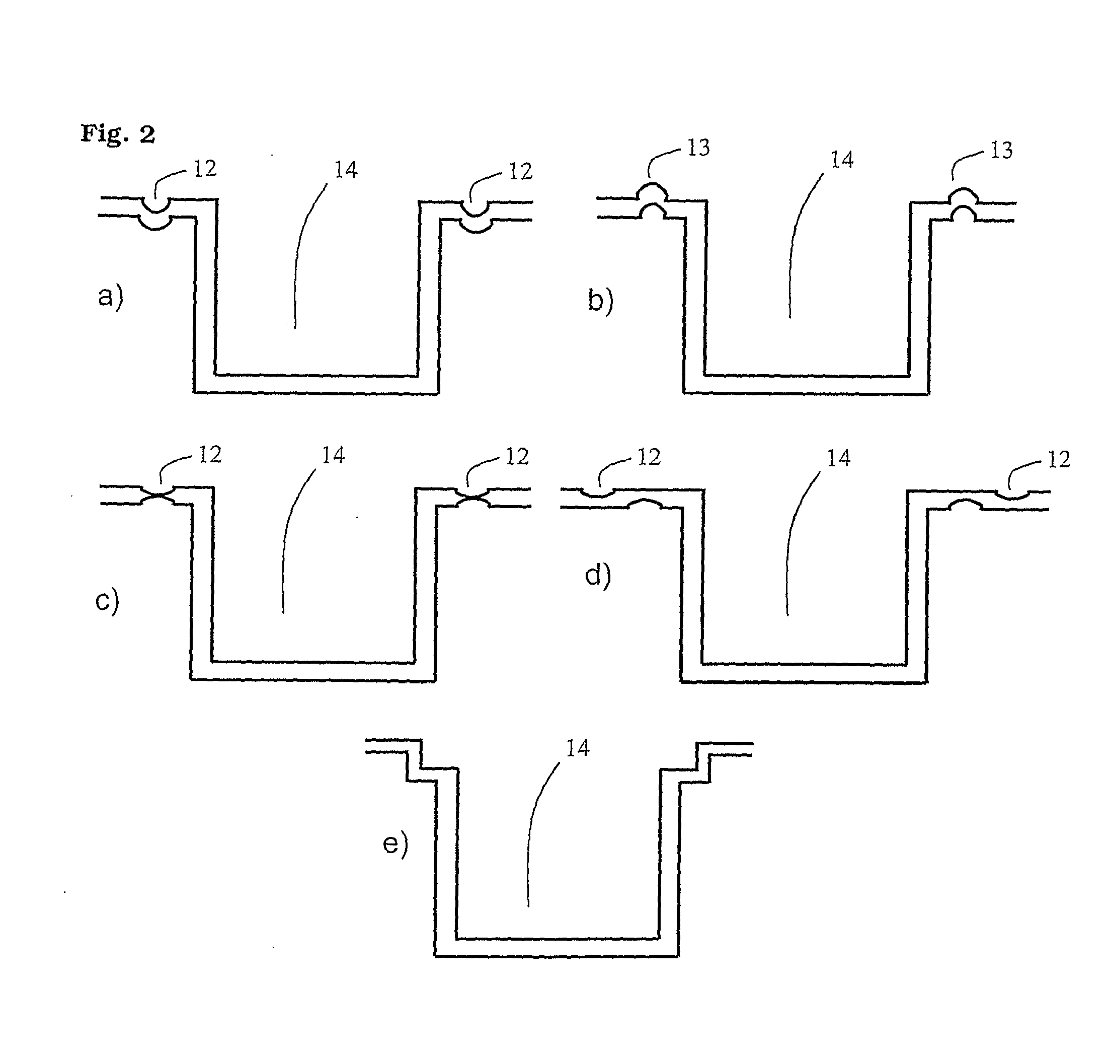
The present invention provides a microtitre plate with wells having transparent bottoms that allow real-time measurements, including simultaneous addition of reactants during the measurements. Cross-talk reduction is accomplished via physical deformations between the wells. The microtitre plate can be manufactured in one piece through conventional processing techniques which means an easy manufacturing process and low production costs.

Problems solved by technology

This phenomenon is caused by internal reflection and transmission of light and results in a false signal from a well where no light signal should be produced.
The result is an incorrect result.
However, these constructions are expensive to produce.
Also, when using such a coating technique, there is a risk of coating the bottom surface of the well.
Additionally, a coating on the inside might affect the desired biological / chemical process in the well.
These solutions will increase the manufacturing cost if a transparent bottom is needed, since the plate needs to be formed with two different materials.
While this microplate reduces the cross-talk between the wells, it also requires a complex multistep production process, which makes it expensive to produce.
However, there is a need for a microtitre plate that is easy to manufacture, is cheap, and still reduces the transmittance and / or reflectance of light when used in analytical methods based on light detection or measurement.

Method used


Image

  • Microtitre plate
  • Microtitre plate
  • Microtitre plate

Examples


examples

Ex. 1

A channel was formed between the wells. This channel stopped a substantial proportion of any light guided through the plastic from entering the neighbouring well.

Two plates were manufactured from the same plastic. Plate 1 had a channel 12 between the wells whereas Plate 2 did not, as shown in FIG. 5.

Wells B6-8 were filled with 20 μl Annealing Buffer used to perform a Pyrosequencing® reaction. Enzyme and substrate for performing Pyrosequencing analysis were added to well B7. Pyrophosphate was dispensed into B7 in Dispensation 2, to give a high signal. Water was dispensed into B6 and B8, which should not give a signal. In this way only Dispensation 2 in well B7 should generate a signal. B6 and B8 were used to measure cross-talk. The dispensations in the wells are described in the table below.

DispensationWell123B6WaterWaterWaterB7WaterPyrophosphateWaterB8WaterWaterWater

The results of the tests are shown below

Cross-talk(signal in B6 or B8)Signal fromAs % ofDispensationpeak inWell12...


PUM

PropertyMeasurementUnit
thickaaaaaaaaaa
transparentaaaaaaaaaa
physical deformationaaaaaaaaaa

Abstract

A microtitre plate with wells having transparent bottoms, wherein the microtitre plate includes at least one physical deformation between at least two adjacent wells. The physical deformations may have the shape of e.g. a channel, a ridge, a hole, a slit or a step.

Description

FIELD OF INVENTIONThe present invention involves a microtitre plate with reduced optical cross-talk between wells. The present invention also relates to such microtitre plates for use in analysis methods using light emission or transmission.BACKGROUNDA large number of biotechnological analysis methods utilize multi-well sample plates, commonly referred to as microtitre plates. Separate reactions are performed in each well and the end products of the reactions are used to interpret the result of the analysis. Alternatively the reactions may be followed in real-time.Such analytical methods may be performed in solution, i.e. all the reactants are present in the solution. If the analyte to be detected is present, the reactants give some sort of signal, such as appearance or change in colour, light emission, turbidity or the like. One example is Pyrosequencing® analysis, which involves detection of light emitted by an enzyme cascade system after incorporation of a nucleotide into a nucle...

Claims


Application Information

Patent Timeline
Patent Type & Authority Applications(United States)
IPC IPC(8): C40B60/00
CPCB01L3/5085B01L2200/141B29C59/002B01L2300/168B01L2300/0829
Inventor SMITH, DAVIDHAGERLID, PETER
Owner QIAGEN INSTR
Learn More