Gas turbine control method and device

a control method and gas turbine technology, applied in the direction of machines/engines, instruments, analogue processes for specific applications, etc., can solve the problems of deviating the actual airflow rate and fuel flow rate of the gas turbine after the commissioning thereof, and the trial operation period is limited, so as to enhance the combustion stability

Active Publication Date: 2011-01-06
MITSUBISHI POWER LTD
View PDF7 Cites 34 Cited by
  • Summary
  • Abstract
  • Description
  • Claims
  • Application Information

AI Technical Summary

Benefits of technology

Thus, the load sensitivity coefficients are calculated while the gas turbine is being operated; the sensitivity analyzing means is provided in order to perform the load sensitivity coefficients calculation. Hence, the intricate procedures for calculating the sensitivity coefficients by manpower are dispensed with; the sensitivity coefficients are automatically calculated concurrently even when the secular change as to the gas turbine performance appears. In this way, the gas turbine can keep and enhance the combustion stability.
Further, the load sensitivity coefficients are calculated while the gas turbine is being operated; the sensitivity analyzing means is provided in order to perform the load sensitivity coefficient calculation. Hence, the intricate procedures for calculating the sensitivity coefficients by manpower are dispensed with; the sensitivity coefficients are automatically calculated concurrently even when the secular change as to the gas turbine performance appears. In this way, the gas turbine can keep and enhance the combustion stability.

Problems solved by technology

However, the period of the trial operation is limited only within a predetermined certain time span; as a matter of course, the trial operations cannot be performed for all the weather conditions that the gas turbine is supposed to encounter.
In addition, the actual airflow rate and the fuel flow rate of the gas turbine after the commissioning thereof may deviate from those at the design stage or the trial operation stage due to the secular change such as the deterioration of the compressor performance or the clogging of filters.
As a result, in a case where unexpected excessive combustion vibrations occur, or in a case where the resonances between the combustion vibrations and the air-column vibrations in the combustor happen, a possibility arises that cracks may be produced on the combustor; the support member may be seriously damaged; the life expectancy as to the configuration members of the gas turbine or the combustor may be reduced.
This practice, however, increases maintenance cost as well as decreases operation availability.
Accordingly, if the air fuel ratio as to the gas turbine operation is controlled based on the vibration countermeasure focusing on the low frequency band as per the approach disclosed by the patent reference 1 (JP1997-269107), then there is a possibility that the combustion vibration status in other frequency bands may become worse.
Summing up the main points as to the patent reference 1, the control device and the method thereof treat with the combustion vibrations of a lower frequency; therefore, if the air fuel ratio as to the gas turbine operation is controlled based on the vibration countermeasure focusing only on the low frequency band, then there is a possibility that the combustion vibration status in other frequency bands may become worse.
On the other hand, according to the disclosure of the patent reference 2, the combustion vibrations relating to the high priority frequency bands can be effectively restrained; however, there may be still a problem; namely, unstable combustion phenomena may happen, for example, due to the aged deterioration of the gas turbine.
However, it is currently known that the automatic change of the actual operation conditions may become a potential cause of unpredictable load fluctuations.

Method used


Image

  • Gas turbine control method and device
  • Gas turbine control method and device
  • Gas turbine control method and device

Examples


first embodiment

In the first place, a gas turbine 2 is briefly explained in relation to FIG. 12 that shows the configuration of the gas turbine 2 as well as FIG. 13 that shows the outline cross section as to the configuration of the combustor of the gas turbine 2. As shown in FIG. 12, the gas turbine comprises a compressor 22 having a plurality of inlet guide vanes 26, and a gas-turbine body 21 having a turbine 24 connected to the compressor 22 and to a generator 40 as an example of a driven gear, via a rotating shaft 39, thereby a combustor 23 supplies the combustion gas to the turbine 24 through a combustion gas introduction tube 38, and the combustion gas is discharged outside through a piping system.

The rotational movement of the turbine 24 is transferred to the compressor 22 through the rotating shaft 39. The compressor inhales ambient air 25 through an air suction port provided with a filter (not shown) for generating compressed air, and the generated compressed air is supplied to the combust...

second embodiment

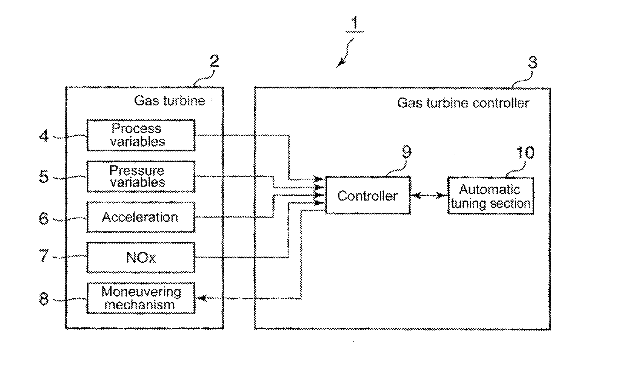
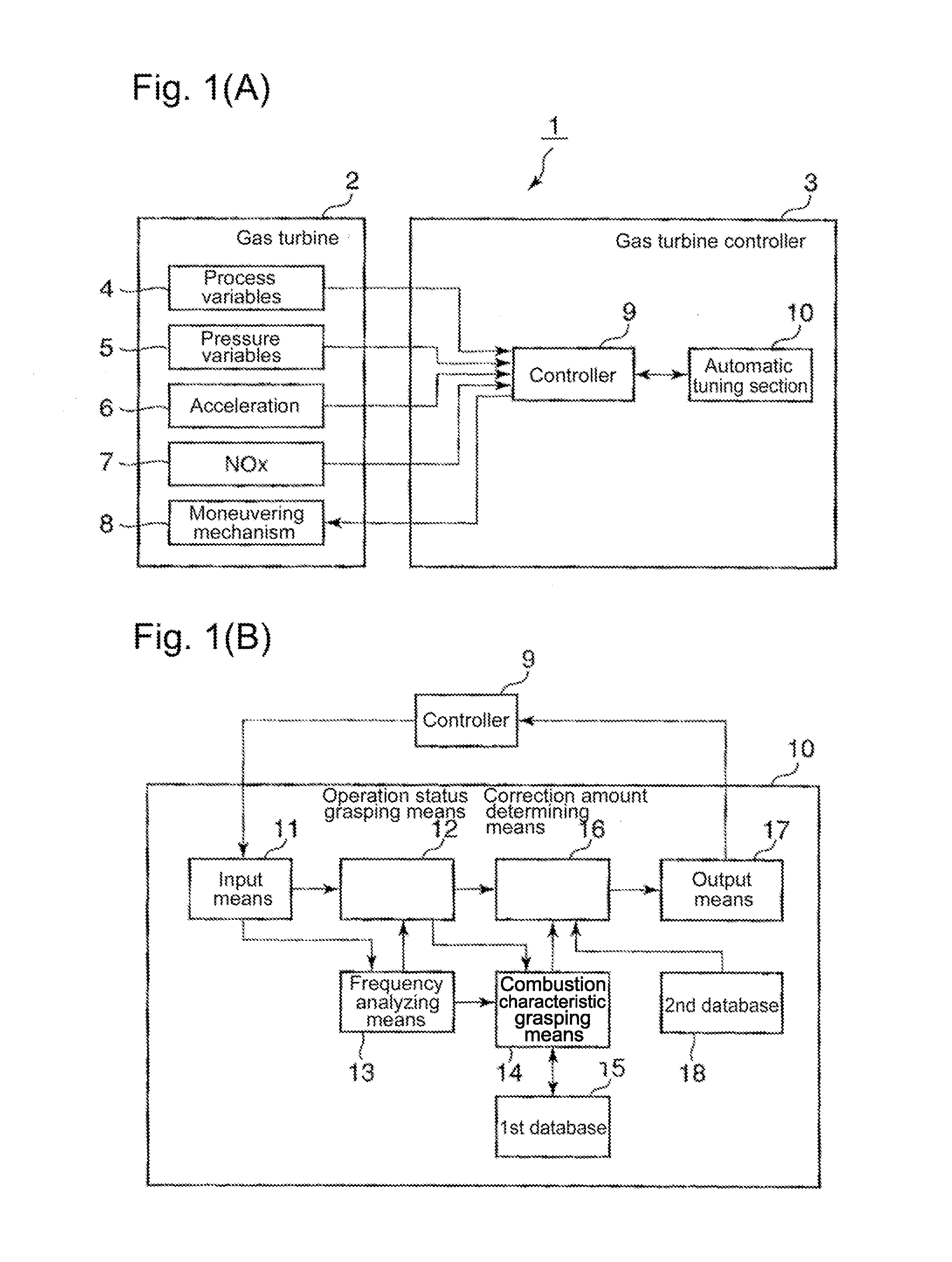
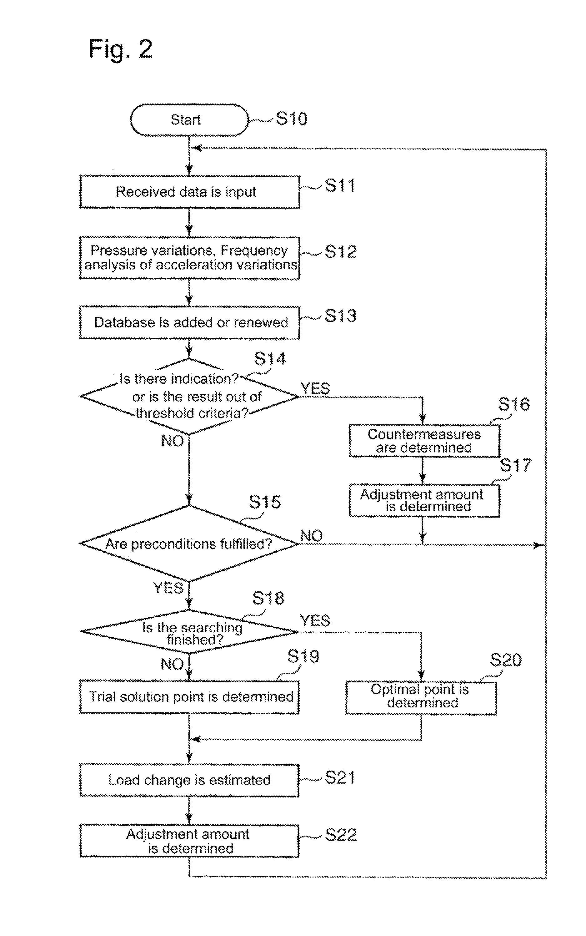
In the next place, the second embodiment according to the present embodiment is now explained in consultation with FIGS. 3, 4 and 9. FIG. 3 is a detailed block diagram as to an automatic tuning section 10 in relation to FIG. 1(A) that shows the functional configuration as to the gas turbine control method according to the present invention; FIG. 4 shows a flow diagram as to a gas turbine control method of a second embodiment according to the present invention; FIG. 9 shows a configuration example as to a database used in the second embodiment according to the present invention.

In the first embodiment that has been explained, the data as to the sensitivity coefficients are collected beforehand, and the obtained data and the numerical (alphanumeric) values thereof are stored in the second database 18 so as to be used for the gas turbine control. In this manner, however, the calculations and the calculated-data storage as to the sensitivity coefficients depend on the manpower; thereby,...


PUM


Abstract

Provided is a gas turbine control method and control device whereby a design performance and an operating state based on ideal fuel flow rate and air flow rate simulated at the time of designing can be maintained by preventing an operation deviated from an operating condition that is based on ideal fuel flow rate and air flow rate simulated by initial design values, in a gas turbine control method designed to search optimal operating conditions automatically using control inputs such as a pilot ratio. The gas turbine controller comprises a second database that stores load sensitivity, i.e. the correlation between the load amount of a gas turbine and control inputs such as a fuel flow rate, air flow rate, pilot fuel ratio, and top hat fuel ratio in the gas turbine, wherein the amount of load variation for at least one of control inputs, a fuel flow rate or an air flow rate supplied to a combustor is predicted according to operational conditions obtained by searching using the load sensitivity, regulation is made according to the prediction results, and the regulation results are stored in the second database.

Description

BACKGROUND OF THE INVENTION1. Field of the InventionThe present invention relates to a control method and a control device of a gas turbine. More concretely, the present invention relates to a gas turbine control method and a control device thereof for controlling the gas turbine so as to prevent the gas turbine from being operated under a irregular condition due to an adjustment operation for restraining combustion vibrations during the operation of the gas turbine, which is a condition deviated from a regular operation condition based on an ideal fuel flow rate and airflow rate that are simulated at the design stage of the gas turbine.2. Background of the InventionFor instance, in a gas turbine driving a generator (an AC generator), the airflow rate and the fuel flow rate toward the combustors of the gas turbine are determined based on the load (the power required by the generator), the ambient temperature, the ambient humidity and so on; and, the airflow rate and the fuel flow ra...

Claims


Application Information

Patent Timeline
Patent Type & Authority Applications(United States)
IPC IPC(8): F02C9/00F02C9/28F02C7/057
CPCF02C9/28F05D2270/44F02C9/50F02C9/34
Inventor NOMURA, MASUMITOYAMA, KOZO
Owner MITSUBISHI POWER LTD
Why Eureka
Try Eureka