Process Tanks in Combination with a Float Magnetostrictive Level Detector

a level detector and process tank technology, applied in liquid/fluent solid measurement, instruments, machines/engines, etc., can solve the problems of difficult and accurate detection of fluid levels, unsuitability of direct detectors, ultrasonic, guided wave and other direct detectors, etc., and achieve the effect of steady level measuremen

Active Publication Date: 2011-01-13
ABB INC
View PDF8 Cites 36 Cited by
  • Summary
  • Abstract
  • Description
  • Claims
  • Application Information

AI Technical Summary

Benefits of technology

The invention is a process tank containing a direct level magnetostrictive measurement system disposed directly in the tank, where the level system preferably communicates to a remote location. One embodiment of the invention embodies an internal float well guide or chamber, which while exactly replicating the actual vessel's internal conditions (pressure and temperature), also prevents the float from being affected by turbulence from a two phase condition (boiling or flashing) inside the vessel. The float well blocks the rising bubbles from entering the float chamber, allowing only liquid to enter, thus replicating the exact hydrostatic head of the two phase fluid internal to the vessel. Since heat is not added in the internal portion of the chamber, flashing or boiling can not occur internally in the float well, and the float has a relatively undisturbed environment, producing a very steady level measurement. The tank may be a flashing process tank, or a process tank (not necessarily flashing) where the internal tank process temperature varies more than 50° C. from the ambient external tank temperature.

Problems solved by technology

One type of application where level detectors are used with unsatisfactory results is in process tanks designed for flashing of a fluid (boiling).
For instance, high pressure steam boiler tanks, heat exchangers (such as a propylene heat exchangers) or cryogenic cooling applications present level detection problems because the fluid is boiling, making accurate detection of fluid levels difficult.
Ultrasonic, guided wave and other direct detectors are generally unsuitable due to the turbulence at the vapor / liquid interface due to flashing.
Additionally, the environment is harsh, commonly configured with high or low process temperatures, and high process pressures.
Failure to maintain liquid levels accurately can result in loss of efficiencies if too low, and possible harm to process equipment if too high.
For instance, in a steam boiler application, if the liquid water level is too low, inefficiency occurs because of lower than designed exchange contact area, and if the water level is too high, liquid droplets with entrained impurities can carry over to the generating equipment, reducing turbine blade life.
However, the differential pressure cell based system is inherently inaccurate.
This non-stable fluid density (specific gravity) is a source of errors in DP cell level detector systems.
However, when conditions change, (e.g. the external environment changes or the in-tank conditions change) the calibrated factor will not be correct, resulting in erroneous level readings within the tank.
One problem with these prior art level measurement technologies is the inability to replicate internal vessel conditions externally from the vessel with non-varying accuracy.
While the effects of internal specific gravity changes can be corrected and compensated for, temperature gradients in external float system chambers, a displacer chambers or differential pressure impulse lines cannot.
Therefore, level measurement errors occur, many times going unnoticed and producing undesired results for long periods of time.
Process tanks where ambient temperatures differ from the process temperatures by at least 50° C. have similar problems with level detection as are present in flashing process tanks.

Method used


Image

  • Process Tanks in Combination with a Float Magnetostrictive Level Detector
  • Process Tanks in Combination with a Float Magnetostrictive Level Detector
  • Process Tanks in Combination with a Float Magnetostrictive Level Detector

Examples


Embodiment Construction

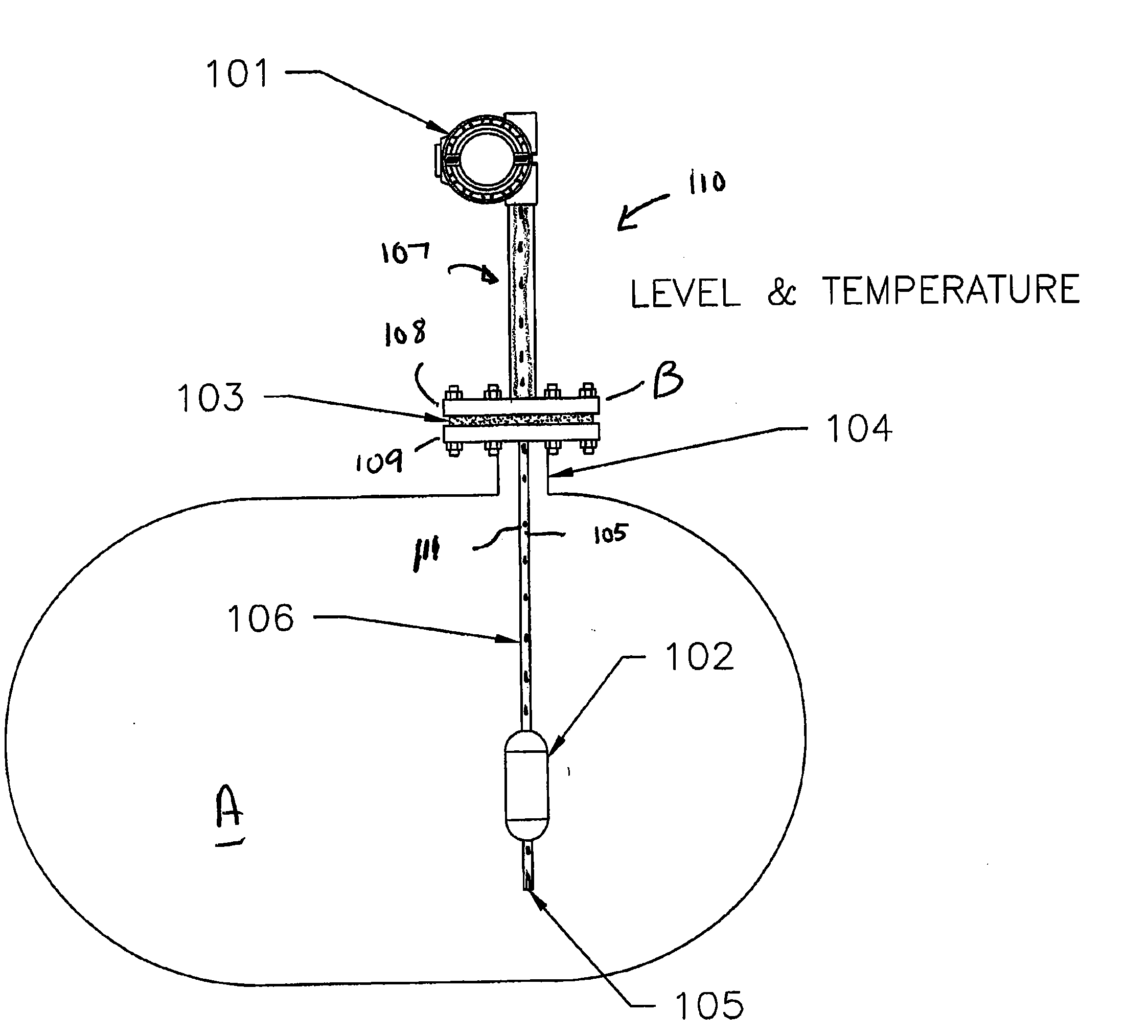
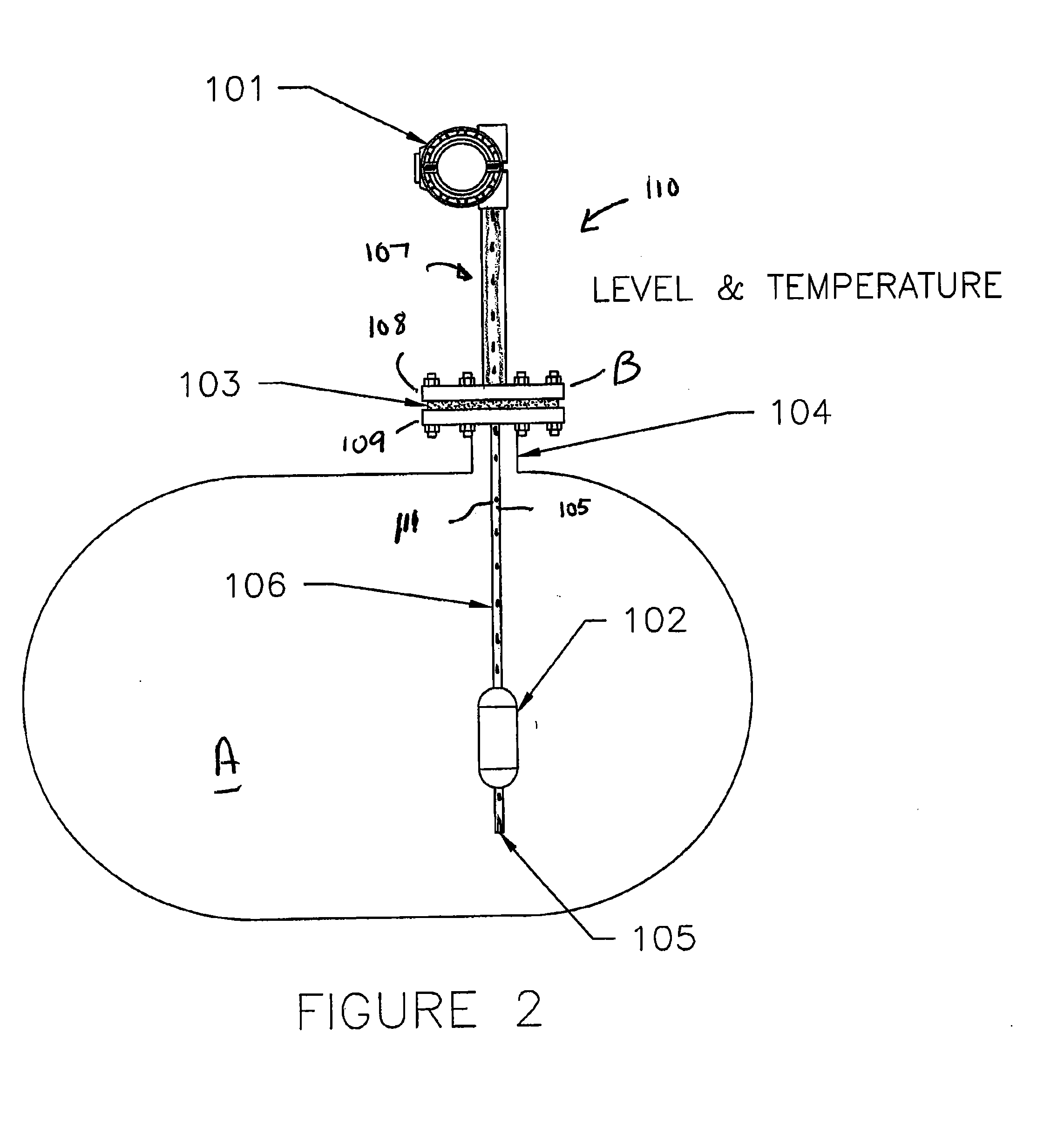
FIG. 2 is a schematic of a flashing process tank with a direct level measurement device installed therein. Not shown on any of the drawings is the direct read visual indicator (sightglass), which is required by code in a boiler application. Tank A has a level detection system 110 with the sensors contained within the tank interior, and not in an external chamber. The level sensor system 110 requires a single flanged area 103 on the tank, as the system 110 combines a level sensor with a temperature probe 105 in a single probe. The level detection system 110 includes a magnetostrictive level sensor that uses a float 102 with internal magnet(s) that interacts with a magnetostrictive wire 111 contained in the guide well or sensing tube 106. The guide well 106 is a sealed tube, and hence the interior of the tube (including the wire 111) is not exposed to the tank process liquid. Attachment of the sensor to the flange joint will be discussed separately.

The operations of a magnetostrictive...


PUM


Abstract

The invention is a process tank containing a direct level magnetostrictive measurement system disposed directly in the tank, where the level system preferably communicates to a remote location. One embodiment of the invention embodies an internal well guide chamber, which exactly replicates the actual vessel's internal conditions (pressure and temperature), and also prevents the float from being affected by turbulence from a two phase condition, such as might occur if boiling or flashing is present inside the vessel. The process tank should have a fluid temperature different by more than 50° C. form the ambient environment, or alternatively, be a flashing tank.

Description

FIELD OF INVENTION Process tanks in Combination with a Float Magnetostrictive Level DetectorBACKGROUND OF THE INVENTION Many industries utilized tanks to process or store liquids, and use level detectors to determine the fluid level within the tank. Level detectors are well known in the art and include magnetostrictive level detectors, float level detectors, guided wave radar level detectors, ultrasonic level detectors, float / magnet combination level detectors, and other similar devices.One type of application where level detectors are used with unsatisfactory results is in process tanks designed for flashing of a fluid (boiling). For instance, high pressure steam boiler tanks, heat exchangers (such as a propylene heat exchangers) or cryogenic cooling applications present level detection problems because the fluid is boiling, making accurate detection of fluid levels difficult. Ultrasonic, guided wave and other direct detectors are generally unsuitable due to the turbulence at the v...

Claims


Application Information

Patent Timeline
Patent Type & Authority Applications(United States)
IPC IPC(8): G01F23/38
CPCG01F23/0046G01F23/30G01F23/72G01F23/62G01F23/40
Inventor HOPPER, HENRY
Owner ABB INC
Why Eureka
Try Eureka