Method for testing fatigue in hydrogen gas

a hydrogen gas and fatigue testing technology, applied in the direction of instruments, using mechanical means, and analysing solids using sonic/ultrasonic/infrasonic waves, etc., can solve the problems of crack formation on the surface of the test piece, large quantity of fretting oxide formed, and crack growth under later load conditions cannot be confirmed, so as to achieve greater efficiency in fatigue testing

Inactive Publication Date: 2011-01-13
NAT INST OF ADVANCED IND SCI & TECH
View PDF10 Cites 10 Cited by
  • Summary
  • Abstract
  • Description
  • Claims
  • Application Information

AI Technical Summary

Benefits of technology

[0011]The present invention was conceived in light of this problem, and it is an object thereof to provide a technique with which various crack growth situations related to a plurality of load conditions can be confirmed in a single fatigue test, which is based on a phenomenon whereby the cycle rate (frequency) of a test is varied, which changes the effect that the hydrogen in the test piece (the hydrogen that has permeated the test piece and / or the hydrogen contained beforehand in the test piece) has on the growth of a crack, which forms different fatigue fracture surfaces. In particular, there is provided a technique for acquiring various fatigue crack growth curves related to a plurality of cycle rates in a single fatigue test.
[0023]With the present invention, however, there is no need to form a fretting oxide. Specifically, even when the fatigue test is conducted in a hydrogen gas atmosphere, it is possible to specify the various crack lengths related to a plurality of cycle rate conditions on the basis of differences in fatigue fracture surface morphologies. Consequently, there is no need to remove and replace the test piece in a hazardous environment such as a high-pressure hydrogen atmosphere, nor is it necessary for the high-pressure hydrogen gas to be removed and replaced, so there are advantages in cost and safety.
[0024]From this standpoint, the present invention is particularly effective in tests conducted in the high-pressure hydrogen gas environments required by fuel cell vehicles that are being developed (the pressure of the hydrogen gas is currently 35 MPa, but is projected to reach 70 MPa in the future). In a test such as these, since the high-pressure hydrogen gas is enclosed in a thick-walled pressure vessel, it is difficult to use conventional optical or electrical crack length measurement techniques, but with the present invention, it is possible to specify the various crack lengths related to a plurality of cycle rate conditions, even under an environment such as this, and there is no need for the test piece to be removed and replaced, etc., nor is it necessary for the high-pressure hydrogen gas to be removed and replaced, so there are advantages in cost and safety.
[0027]Furthermore, with the present invention, it is possible to specify various crack lengths related to a plurality of load conditions in a single fatigue test, so it is possible to acquire various fatigue crack growth curves related to the plurality of conditions, which contributes significantly to greater efficiency in fatigue testing.

Problems solved by technology

First, a crack is formed on the surface of the test piece.
This is because if the crack growth rate is decreased too much, there will be a large quantity of fretting oxide formed, which is due to repeated contact with the fracture surface.
Specifically, although crack growth under the initial load conditions can be confirmed from the fatigue fracture surface of the test piece, a problem is that crack growth under the later load conditions cannot be confirmed.
As for the later cycle rate (f2=1 Hz), a fatigue crack growth curve has to be acquired at this cycle rate and by setting the number of cycles and the stress amplitude so that the crack will grow, and then conducting another fatigue test with a separate test piece, which is inefficient.

Method used


Image

  • Method for testing fatigue in hydrogen gas
  • Method for testing fatigue in hydrogen gas
  • Method for testing fatigue in hydrogen gas

Examples


Embodiment Construction

[0039]1. Effect of Hydrogen Contained in Test Piece

[0040]First, the effect that the hydrogen contained in a test piece has on fatigue crack growth will be described.

[0041]Hydrogen is known to permeate a metal material and lower its static strength and fatigue strength (see the above-mentioned Non-Patent Documents 1 and 2, for example). The inventors of the present invention conducted the following experiment, and confirmed how much effect the hydrogen contained in a test piece has on the growth rate of fatigue cracks.
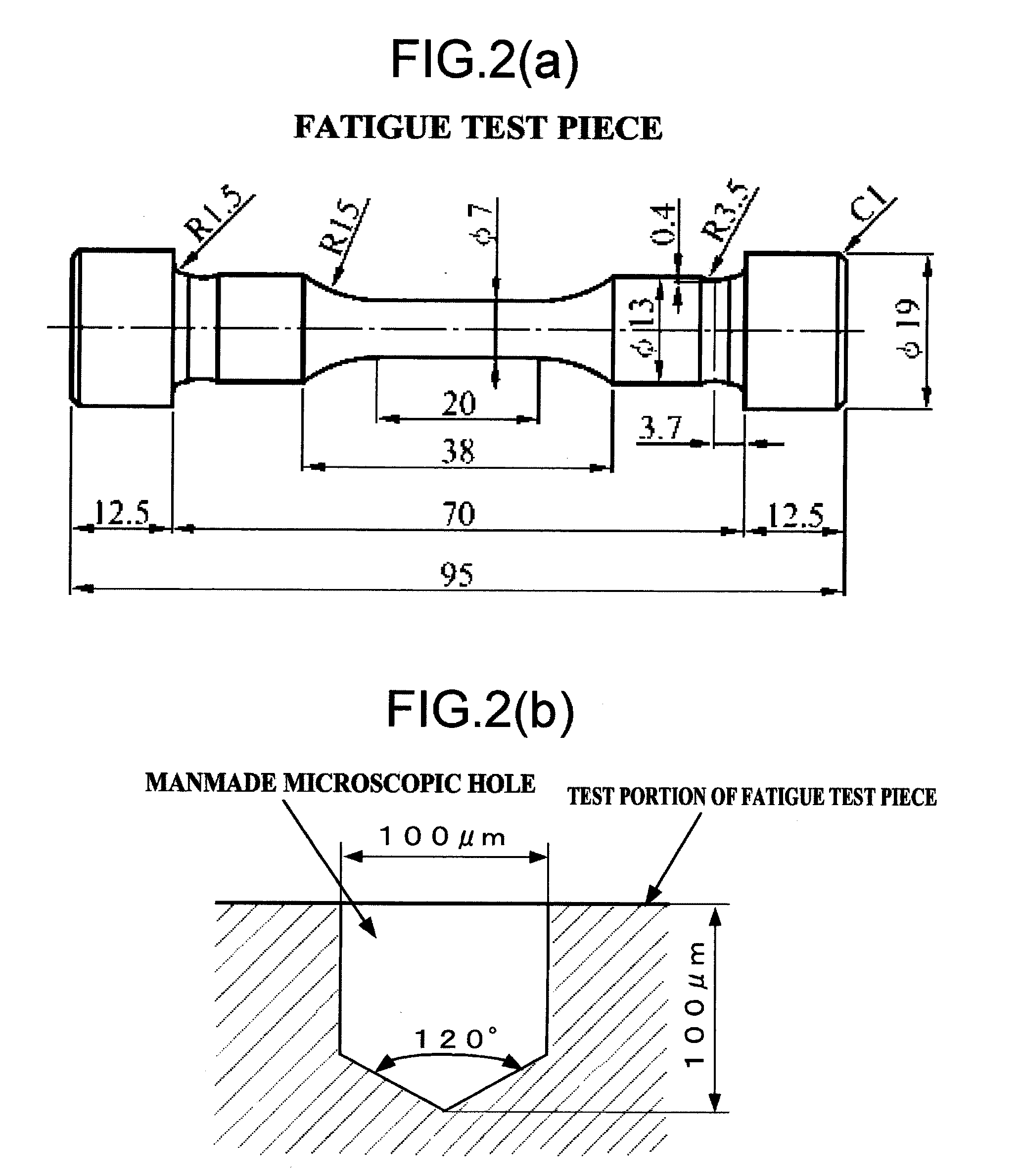
[0042]Test Piece

[0043]The materials used were austenitic stainless steel SUS 304, SUS 316, and SUSU 316L (A) (hereinafter referred to simply as SUSU 316L). SUS 304, SUS 316, and SUSU 316L that had undergone solid solution treatment were used. FIG. 2(a) shows the shape of the test piece. The surface of the test piece was polished with a #2000 emery cloth, then finished by buffing. Two kinds of test piece were prepared, those that had been hydrogen-charged (see below) and...


PUM

PropertyMeasurementUnit
pressureaaaaaaaaaa
pressureaaaaaaaaaa
crack lengthaaaaaaaaaa

Abstract

There is provided a fatigue test method with which the crack growth can be checked for a plurality of cycle rates in a single test. At a first cycle rate f1 of 0.01 Hz, hydrogen has a greater effect on crack growth than at a second cycle rate f2 of 1 Hz. As a result, an area of large hydrogen effect (an area developed at the cycle rate f1) and an area of small hydrogen effect (an area developed at the cycle rate f2) appear alternately on the fatigue fracture surface, and since these two areas have different fracture surface morphologies, it is possible to see the boundary lines. Consequently, the lengths of the cracks developed under each set of conditions can be specified, and a fatigue crack growth curve can be acquired for each set of conditions.

Description

TECHNICAL FIELD[0001]This invention relates to a fatigue test method for specifying the length of cracks developed under specific conditions from the fatigue fracture surface of a test piece.BACKGROUND ART[0002]As discussed in Patent Document 1, a conventional fatigue test method for checking the crack growth imparted to a test piece involved making a beach mark on the test piece. A beach mark is usually made by the following procedure.[0003]First, a crack is formed on the surface of the test piece. Then, as shown in FIG. 1(a), a load is imparted at a specific number of cycles, a specific stress amplitude, and a specific cycle rate at which this crack will grow. In the example in FIG. 1(a), the cycle rate is f1 (=0.01 Hz), the stress amplitude is σ1, and the number of cycles is N1.[0004]Next, in making the beach mark, the cycle rate and / or the stress amplitude is changed to a value that is different from that in the first set of conditions mentioned above, and the load is imparted. ...

Claims


Application Information

Patent Timeline
Patent Type & Authority Applications(United States)
IPC IPC(8): G01N19/08
CPCG01N3/34G01N2203/027G01N2203/0242G01N2203/0066
Inventor MATSUOKA, SABUROMURAKAMI, YUKITAKAKANEZAKI, TOSHIHIKO
Owner NAT INST OF ADVANCED IND SCI & TECH
Why Eureka
Try Eureka