Waste heat recovering device

a heat recovery and waste heat technology, applied in the direction of indirect heat exchangers, machines/engines, light and heating apparatus, etc., can solve the problems of excessive heat recovery, difficult to completely recover heat from these heat sources, and ineffective catalytic functions, etc., to achieve efficient waste heat recovery

Inactive Publication Date: 2011-01-13
ISUZU MOTORS LTD
View PDF6 Cites 63 Cited by
  • Summary
  • Abstract
  • Description
  • Claims
  • Application Information

AI Technical Summary

Benefits of technology

[0011]The present invention demonstrates an excellent effect of enabling efficient

Problems solved by technology

However, heat of exhaust gas of an internal combustion engine that is used as the main heat source is also used as energy for activating a catalyst of a subsequent stage, and where the heat is excessively recovered from the exhaust gas, the catalyst cannot function effectively.
Further, in addition to exhaust gas, an internal combustion engine in

Method used


Image

  • Waste heat recovering device
  • Waste heat recovering device
  • Waste heat recovering device

Examples


Embodiment Construction

[0019]The preferred embodiment of the present invention will be described below in greater detail with reference to the appended drawings.

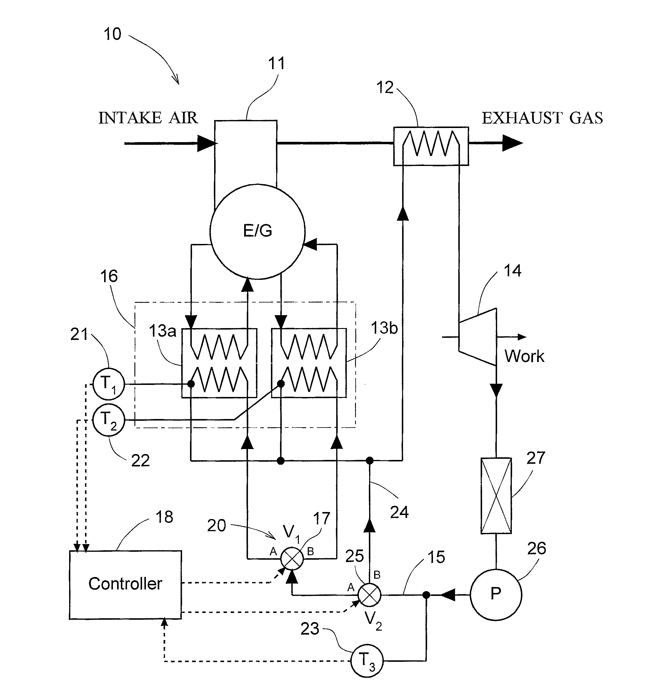
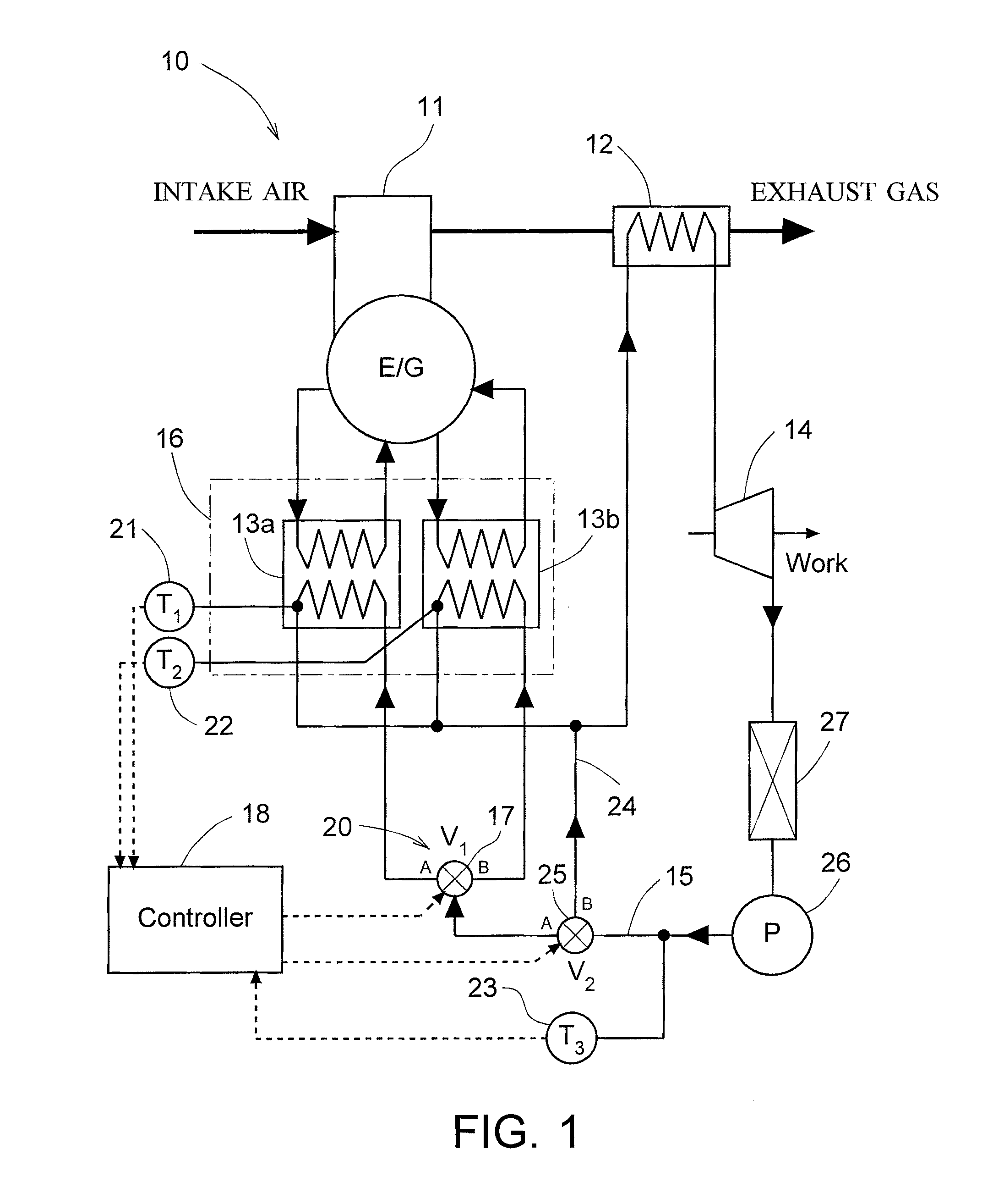
[0020]As shown in FIG. 1, a waste heat recovering device 10 according to the present embodiment serves to recover waste heat of an internal combustion engine (diesel engine and the like) 11 installed on a vehicle. The waste heat recovering device is provided with an expander 14 driven by steam generated by the below-described high-temperature heat exchanger 12 and low-temperature heat exchangers 13a, 13b. A generator (not shown in the figure) is actuated by the expander 14, and the electric power generated by the generator is consumed for driving various devices by the below-described controller 18 and accumulated by a battery.

[0021]The waste heat recovering device 10 of the present embodiment includes a working fluid circulation flow path 15 in which the working fluid of the expander 14 is caused to circulate, a high-temperature heat exchanger 12...


PUM


Abstract

The present invention provides a waste heat recovering device capable of recovering waste heat with good efficiency from various heat sources in an internal combustion engine. The waste heat recovering device for driving an expander 14 by evaporating a working fluid by waste heat of an internal combustion engine 11 includes: a working fluid circulation flow path 15 in which the working fluid of the expander 14 is caused to circulate; a high-temperature heat exchanger 12 for heating the working fluid flowing in the working fluid circulation flow path 15 by a high-temperature fluid such as exhaust gas of the internal combustion engine 11; a low-temperature heat exchanger group 16 having, for each of low-temperature fluids such as cooling water and oil of the internal combustion engine 11, a low-temperature heat exchanger 13a, 13b for heating the working fluid flowing in the working fluid circulation flow path 15 by any one of the low-temperature fluids, the low-temperature heat exchangers 13a, 13b being disposed in parallel with each other; a flow rate control valve 17 that controls a flow rate of the working fluid flowing into each low-temperature heat exchanger 13a, 13b of the low-temperature heat exchanger group 16; and control means 18 for controlling the flow rate control valve 17.

Description

CROSS REFERENCE TO RELATED APPLICATIONS[0001]This application is entitled to the benefit of and incorporates by reference essential subject matter disclosed in International Patent Application No. PCT / JP2009 / 052673 filed on Feb. 17, 2009 and Japanese Patent Application No. 2008-083483 filed Mar. 27, 2008.TECHNICAL FIELD[0002]The present invention relates to a waste heat recovering device for driving an expander by evaporating a working fluid by waste heat of an internal combustion engine.BACKGROUND ART[0003]A composite cycle in which an internal combustion engine is combined with an external combustion engine to use effectively the waste heat of the internal combustion engine has been widely employed in power generation facilities (see Japanese Patent Application Publication No. 2004-257601 and Japanese Patent Application Publication No. S63-147549). Recently an attempt has also been made to use such a cycle in an internal combustion engine of a vehicle.DISCLOSURE OF THE INVENTION[0...

Claims


Application Information

Patent Timeline
IPC IPC(8): F01P3/20F28D15/00F01N5/02
CPCF01K23/065F01N5/02F01N2240/02Y02T10/166F02G2260/00F02G2262/00Y02T10/16F02G5/04Y02T10/12
Inventor TERASHIMA, KOJIABE, MAKOTOYAMAMOTO, YASUSHI
Owner ISUZU MOTORS LTD
Why Eureka
Try Eureka