Fuel injection system

Inactive Publication Date: 2011-01-13
VOLVO LASTVAGNAR AB
View PDF7 Cites 10 Cited by
  • Summary
  • Abstract
  • Description
  • Claims
  • Application Information

AI Technical Summary

Benefits of technology

[0002]Fuel injection systems of internal combustion engines, in particular systems for injection of fuel directly into combustion cylinders of compression ignition engines, may be featuring a control valve for pressure relief from a nozzle of an injector for injecting fuel into a combustion chamber of the internal combustion engine. Such solutions are typically applied in common rail injection systems for preventing a leakage of fuel through a closed nozzle, which is otherwise difficult to avoid when using low viscosity fuels such as DME.
[0003]An example of such a system known from prior art is shown in FIG. 1. In that system, designed for operation with DME, there are automatic isolating valves (AIV) employed for preventing leakage of fuel from the fuel supply system through closed nozzles into engine's cylinders when the engine is stopped. These automatic isolating valves are referenced to ambient pressure and are designed to be open when the fuel feed pump is ON and the pressure at the return line of the injectors is higher than DME vapour pressure, and to be closed to prevent access of DME to injectors when the feed pump is OFF. The description of a typical AIV is given, for example, in U.S. Pat. No. 6,189,517 B1. One of the AIVs is placed at the high-pressure port of each of the injectors. The return lines of the injectors are connected together and a common low-pressure AIV is placed downstream of that connection. By this means, the number of low-pressure AIVs is kept to a minimum to make the fuel injection system simpler. It is also known from prior art to position the high-pressure AIV directly upstre

Problems solved by technology

Such solutions are typically applied in common rail injection systems for preventing a leakage of fuel through a closed nozzle, which is otherwise difficult to avoid when using low viscosity fuels such as DME.
It is also known from prior art to position the high-pressure AIV directly upstream of the nozzle, but that design leads to increased control leakage and worse injection controllability at small injected quantities because of the associated volume increase in the high-pressure circuit that is drained between injections.
However, in that prior art system, the total volume of fuel confined between the nozzle and the AIVs can be relatively large,

Method used


Image

  • Fuel injection system
  • Fuel injection system
  • Fuel injection system

Examples


Embodiment Construction

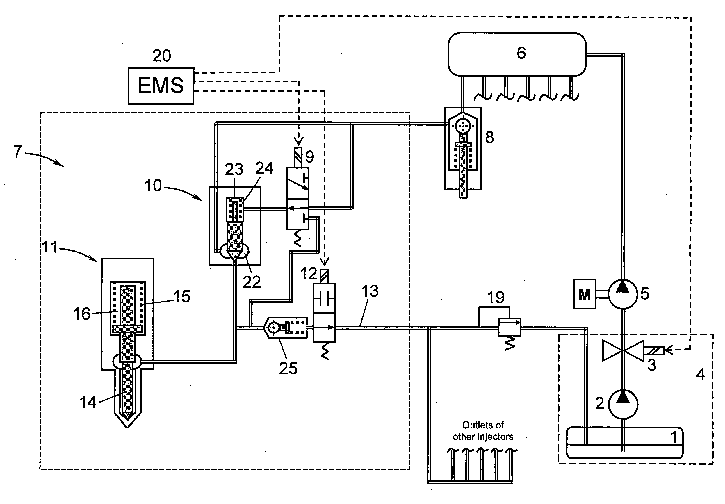
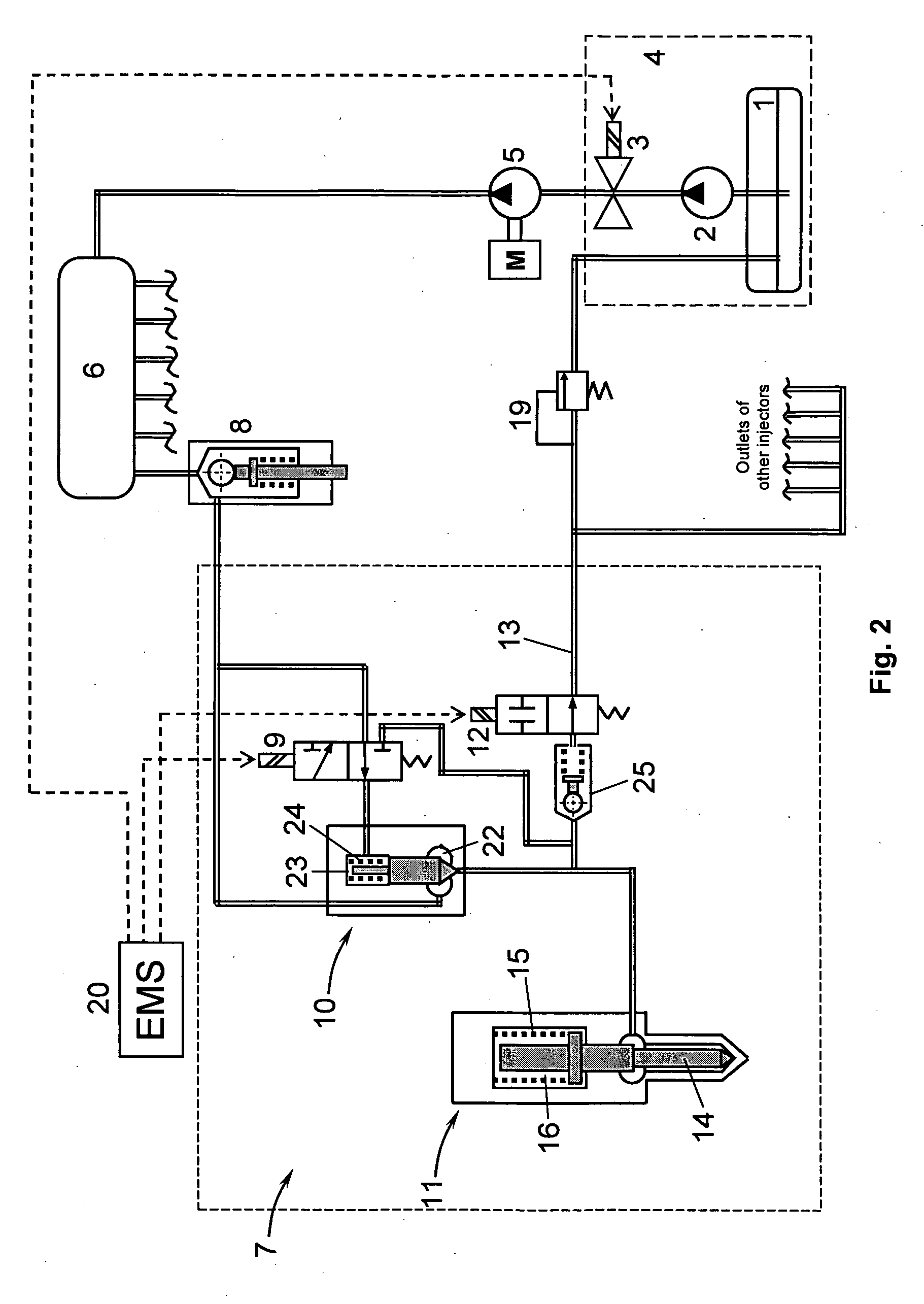
[0022]In an example embodiment shown in FIG. 2, a fuel injection system according to present invention incorporates a fuel tank 1, a feed pump 2, an isolating valve 3 and other associated components (not shown) forming a low-pressure system 4, and a high-pressure pump 5 delivering fuel under pressure into a common rail 6, which supplies pressurised fuel to all injectors 7 of a multi-cylinder engine (not shown). An automatic isolating valve 8 is installed between the common rail 6 and the injector 7, which latter one incorporates a three-way electrically operated pilot valve 9 that controls a hydraulically operated valve 10 positioned between the common rail and a nozzle 11, and an electrically operated, two-way, normally open spill valve 12 positioned between the outlet of the hydraulically operated valve 10 and a return line 13. The nozzle 11 has a needle 14 that is biased by a return spring 15 towards closing the nozzle. The return spring is installed in a spring chamber 16 which,...


PUM


Abstract

A fuel injection system for an internal combustion engine includes an engine management system (EMS), a return line connected to a low-pressure fuel system, a common rail for storing and supplying a relatively high-pressure fuel to an injector, and an automatic isolating valve installed between the common rail and the injector. The injector has a nozzle for injecting fuel into the engine. A valve is operated by the EMS and installed between the common rail and the nozzle. A spill valve is operated by the EMS and connected by its inlet to the outlet of the valve and by its outlet to the return line. A check valve is installed between the nozzle and the return line, the inlet of the check valve being connected to the inlet of the nozzle.

Description

BACKGROUND AND SUMMARY[0001]The present invention relates to a fuel injection system for an internal combustion engine and a vehicle.[0002]Fuel injection systems of internal combustion engines, in particular systems for injection of fuel directly into combustion cylinders of compression ignition engines, may be featuring a control valve for pressure relief from a nozzle of an injector for injecting fuel into a combustion chamber of the internal combustion engine. Such solutions are typically applied in common rail injection systems for preventing a leakage of fuel through a closed nozzle, which is otherwise difficult to avoid when using low viscosity fuels such as DME.[0003]An example of such a system known from prior art is shown in FIG. 1. In that system, designed for operation with DME, there are automatic isolating valves (AIV) employed for preventing leakage of fuel from the fuel supply system through closed nozzles into engine's cylinders when the engine is stopped. These auto...

Claims


Application Information

Patent Timeline
IPC IPC(8): F02M69/46
CPCF02M55/002F02M63/0005F02M63/0029F02M63/0045Y02T10/32F02M63/0265F02M37/0052F02M21/0245F02M63/0215Y02T10/30F02M63/0007F02M63/021
Inventor YUDANOV, SERGI
Owner VOLVO LASTVAGNAR AB
Why Eureka
Try Eureka