Radiation image detection apparatus and manufacturing method of the same

a technology of radiation image and detection apparatus, which is applied in the direction of radiation intensity measurement, x/gamma/cosmic radiation measurement, instruments, etc., can solve the problems of inability to obtain sufficient sensitivity or blurring of an image, scintillator may decrease the yield of an article, and neither sensitivity nor resolution of a produced image are satisfactory, so as to reduce light, not decrease the sharpness of the image, and good film-forming property

Active Publication Date: 2011-01-13
FUJIFILM CORP
View PDF6 Cites 56 Cited by
  • Summary
  • Abstract
  • Description
  • Claims
  • Application Information

AI Technical Summary

Benefits of technology

[0062]In addition, it is preferred to optically combine both by bringing the surface of the side of the formed scintillator layer 18, in which the area of columnar crystals 34 is present, and the optical detector 16 to be opposite to each other via a resin layer. Available examples of the resin layer may include a planarizing layer, which is for planarizing the surface of the scintillator layer 18, an adhesive layer, which fixedly brings both into contact, a matching oil layer, which is made of transparent liquid or gel, and the like. The resin, which forms the resin layer, is not specifically limited as long as it allows scintillation light, which is generated from the scintillator layer 18, to pass through to the optical detector 16 without reducing the light.
[0063]Available examples of the resin, which forms the planarizing layer, may include polyimide, parylene, and the like. Polyimide, which has good film-forming property, is preferable.
[0064]The adhesive agent, which forms the adhesive layer, is not limited to those that are optically transparent to the scintillation light, which is generated from the scintillator layer 18. Available examples of the adhesive agent may include a thermoplastic resin, an Ultraviolet (UV) curing adhesive agent, a thermosetting adhesive agent, a room-temperature curing adhesive agent, a double-sided adhesive sheet, and the like. From the viewpoint of not decreasing the sharpness of the image, it is preferred to use an adhesive agent made of a low-viscosity epoxy resin since it can form an adhesive layer that is sufficiently thin in relation to the pixel size of the optical detector 16.
[0065]In addition, as described above, the thickness of the resin layer is preferably 50 μm or less from the viewpoints of the sensitivity and image and more preferably in the range from 5 μm to 30 μm.
[0066]According to the method as described above, it is possible to efficiently and easily manufacture the radiation image detection apparatus according to an aspect of the invention. In addition, the manufacturing method according to an aspect of the invention also has an advantage capable of simply and easily manufacturing various specifications of scintillator layers according to designs by controlling the degree of vacuum and the temperature of the support in the forming of the film of the scintillator layer.
[0067]Below, the present invention will be described in detail with respect to Examples. However, the present invention is not limited to the detailed Examples.

Problems solved by technology

This causes problems such as being unable to obtain sufficient sensitivity or blurring of an image.
However, there is possibility that the scintillator may decrease the yield of an article due to the need for precision in process control during the manufacturing.
In addition, neither sensitivity nor the resolution of a produced image is satisfactory, and improvement is still demanded.

Method used


Image

  • Radiation image detection apparatus and manufacturing method of the same
  • Radiation image detection apparatus and manufacturing method of the same
  • Radiation image detection apparatus and manufacturing method of the same

Examples


example 1

[0068]1. Forming of Scintillator Layer

[0069]A non-alkali glass substrate (0.7 mm thick) was prepared as a support.

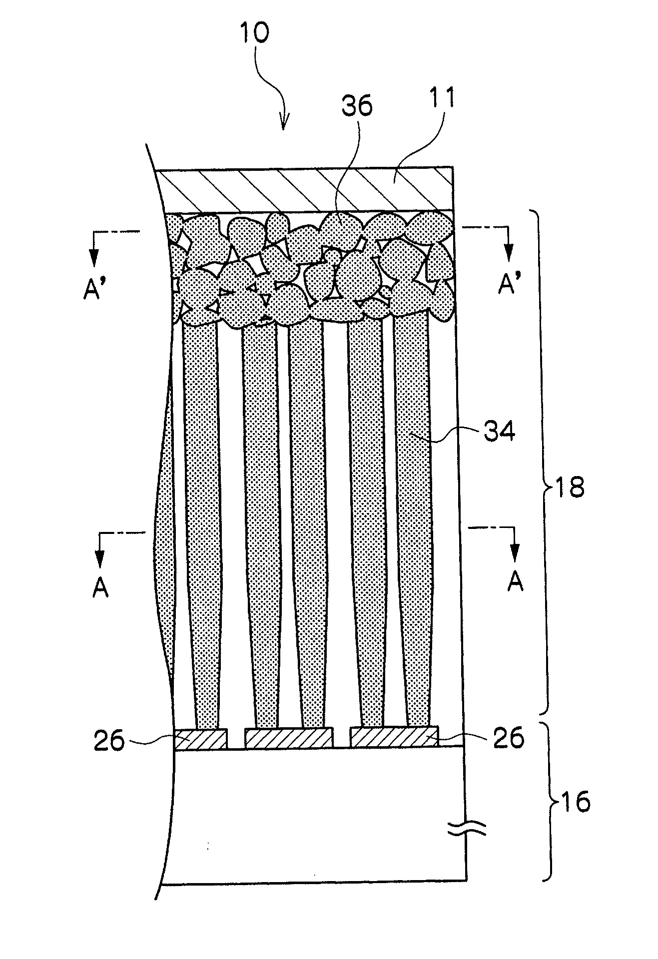
[0070]First, a support was surface-treated using Ar plasma for the purpose of improving adhesiveness with a CsI crystal layer. Afterwards, the surface-treated support was set in a vacuum chamber, which serves to form a scintillator film. The vacuum chamber included plural furnaces, which serve to heat raw materials, that is, CsI and TlI independently. After air was exhausted from the chamber, the degree of vacuum was set to be 0.75 Pa by introducing a certain amount of Ar. At a time point when the melting conditions of the raw materials were stabilized due to heating of the raw material furnaces, the support was rotated on a concentric circle by an apparatus tool of the vacuum apparatus, a shutter was opened, and deposition of an area of non-columnar crystals 36 was started.

[0071]Film-forming was carried out under these conditions, and at a time point when the thickness ...

example 2 to example 6

[0093]Radiation image detection apparatuses of Examples 2 to 6 were manufactured in the same fashion as in Example 1, except for setting the thickness of the non-columnar crystal area in Example 1 according to the description in Table 1 by changing the deposition time when the degree of vacuum was 0.75 Pa, and were evaluated in the same fashion. The results are presented in Table 1 below.

example 7 to example 11

[0094]Radiation image detection apparatuses of Examples 7 to 11 were manufactured in the same fashion as in Example 1, except for forming the film of the non-columnar crystal area in Example 1 by changing the degree of vacuum according to the description in Table 1 so that the crystal diameters in the non-columnar crystal area were the same as the description in Table 1, and were evaluated in the same fashion. The results are reported in Table 1 below.


PUM

PropertyMeasurementUnit
diameteraaaaaaaaaa
diameteraaaaaaaaaa
diametersaaaaaaaaaa

Abstract

A radiation image detection apparatus comprising a scintillator, which is configured to include columnar crystals and converts radiation into light when the radiation is irradiated thereon, and an optical detector, which converts the light, emitted from the scintillator into an electrical signal, the scintillator and the optical detector being arranged on a support such that the radiation is incident on the optical detector and the scintillator in this order, wherein a columnar crystal area is present at a radiation-incident side of the scintillator, and a non-columnar crystal area is present at a side of the scintillator opposite to the radiation-incident side; and a method for manufacturing the radiation image detection apparatus are provided.

Description

CROSS-REFERENCE TO RELATED APPLICATION[0001]This application is based on and claims priority under 35 USC 119 from Japanese Patent Application No. 2009-164205, filed on Jul. 10, 2009, the disclosure of which is incorporated by reference herein.BACKGROUND OF THE INVENTION[0002]1. Field of the Invention[0003]The present invention relates to a radiation image detection apparatus, which is used in an X-ray imaging apparatus for medical use or the like, and a manufacturing method of the same.[0004]2. Description of the Related Art[0005]In recent years, a radiation image detection apparatus, such as a Flat Panel Detector (FPD), capable of directly converting radiation into digital data, has been put to practical use. The radiation image detection apparatus is being rapidly distributed since it has an advantage of being able to immediately verify an image compared to conventional image plates.[0006]Various types of such radiation image detection apparatuses were proposed. For example, an i...

Claims


Application Information

Patent Timeline
Patent Type & Authority Applications(United States)
IPC IPC(8): G01T1/202C23C16/44
CPCG01T1/202G01T1/2018G01T1/20187G01T1/20185G01T1/20186
Inventor SATO, KEIICHIROKITADA, MAKOTOMIURA, KEI
Owner FUJIFILM CORP
Why Eureka
Try Eureka