Motor drive control apparatus, vehicle with motor drive control apparatus, and motor drive control method

a technology of motor drive and control apparatus, which is applied in the direction of motor/generator/converter stopper, dynamo-electric converter control, gearing, etc., can solve the problem of not revealing the method, and achieve the effect of improving the efficiency upon driving

Inactive Publication Date: 2011-01-13
TOYOTA JIDOSHA KK
View PDF10 Cites 37 Cited by
  • Summary
  • Abstract
  • Description
  • Claims
  • Application Information

AI Technical Summary

Benefits of technology

[0005]The motor drive control apparatus, the vehicle with motor drive control apparatus, and the motor drive control method according to the present invention has a main object to appropriately boost a voltage on a side of the motor drive circuit with respect to the voltage on the side of the direct-current power source by a voltage converter so as to improve efficiency upon driving and controlling a motor,
[0024]The method optimally defines the non-boost region in which the voltage on the side of the motor drive circuit is not boosted with respect to the voltage on the side of the direct-current power source and the boost region in which the voltage on the side of the motor drive circuit is boosted with respect to the voltage on the side of the direct-current power source so that the voltage converter appropriately boosts the voltage on the side of the motor drive circuit with respect to the voltage on the side of the direct-current power source, thereby improving the efficiency upon driving and controlling the motor.

Problems solved by technology

However, the Patent Document 1 does not disclose how to define the relationship between the torque command, the rotational speed, and the target boost voltage.

Method used


Image

  • Motor drive control apparatus, vehicle with motor drive control apparatus, and motor drive control method
  • Motor drive control apparatus, vehicle with motor drive control apparatus, and motor drive control method
  • Motor drive control apparatus, vehicle with motor drive control apparatus, and motor drive control method

Examples


Embodiment Construction

[0041]Now, the best mode for carrying out the present invention will be described with reference to an embodiment.

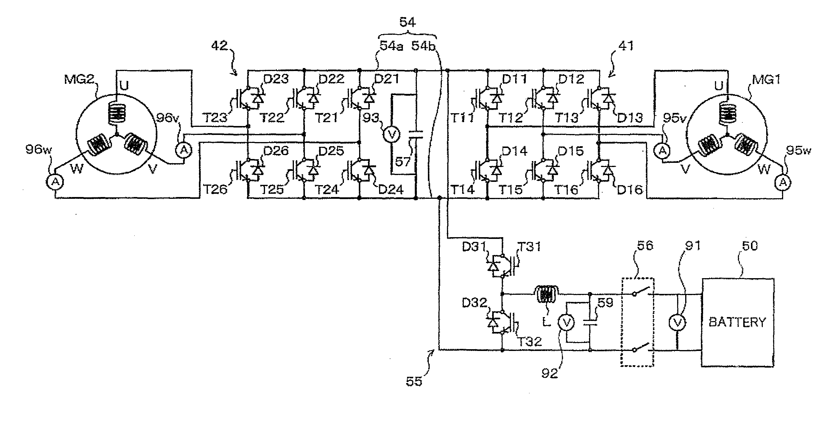
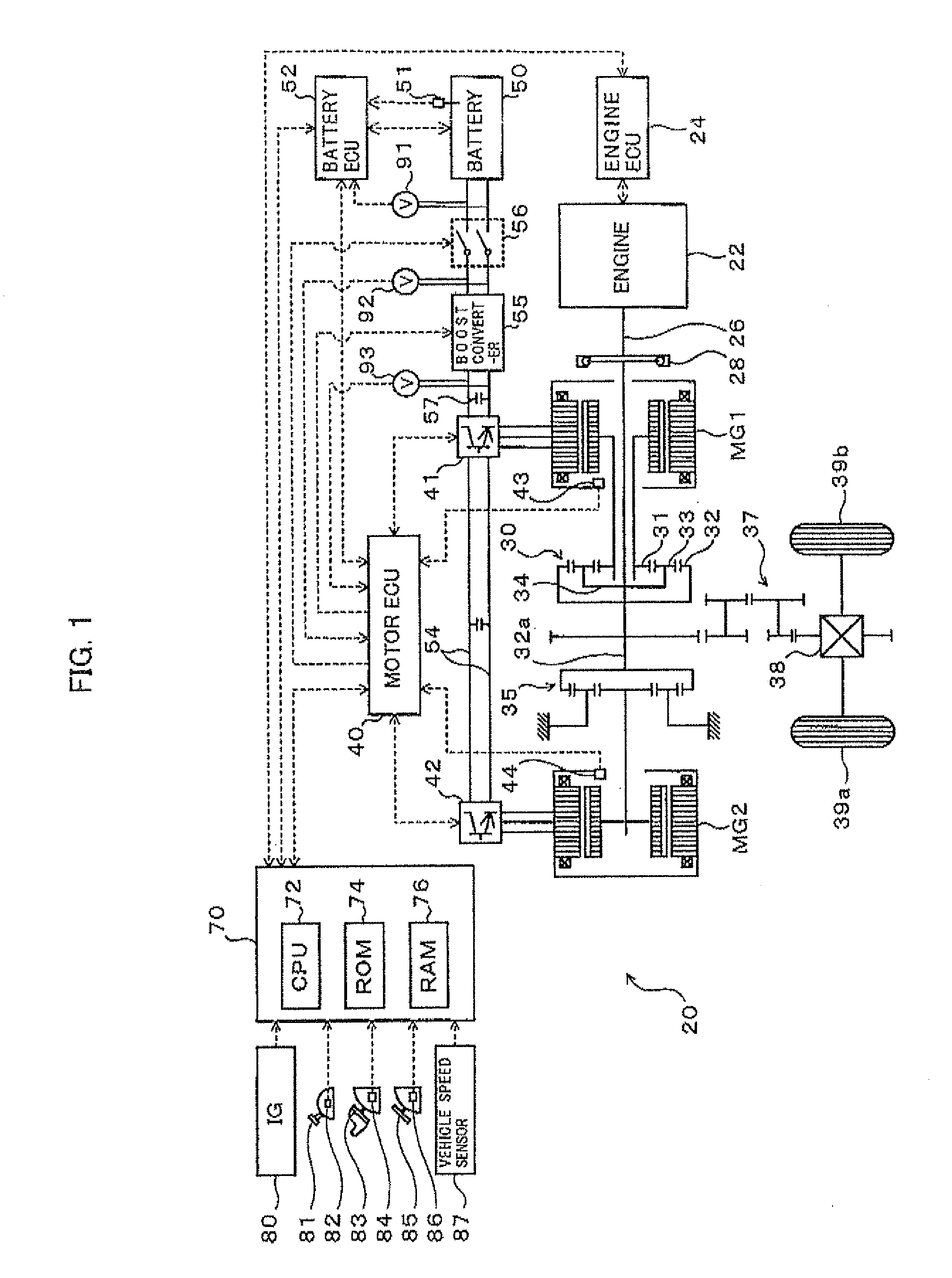
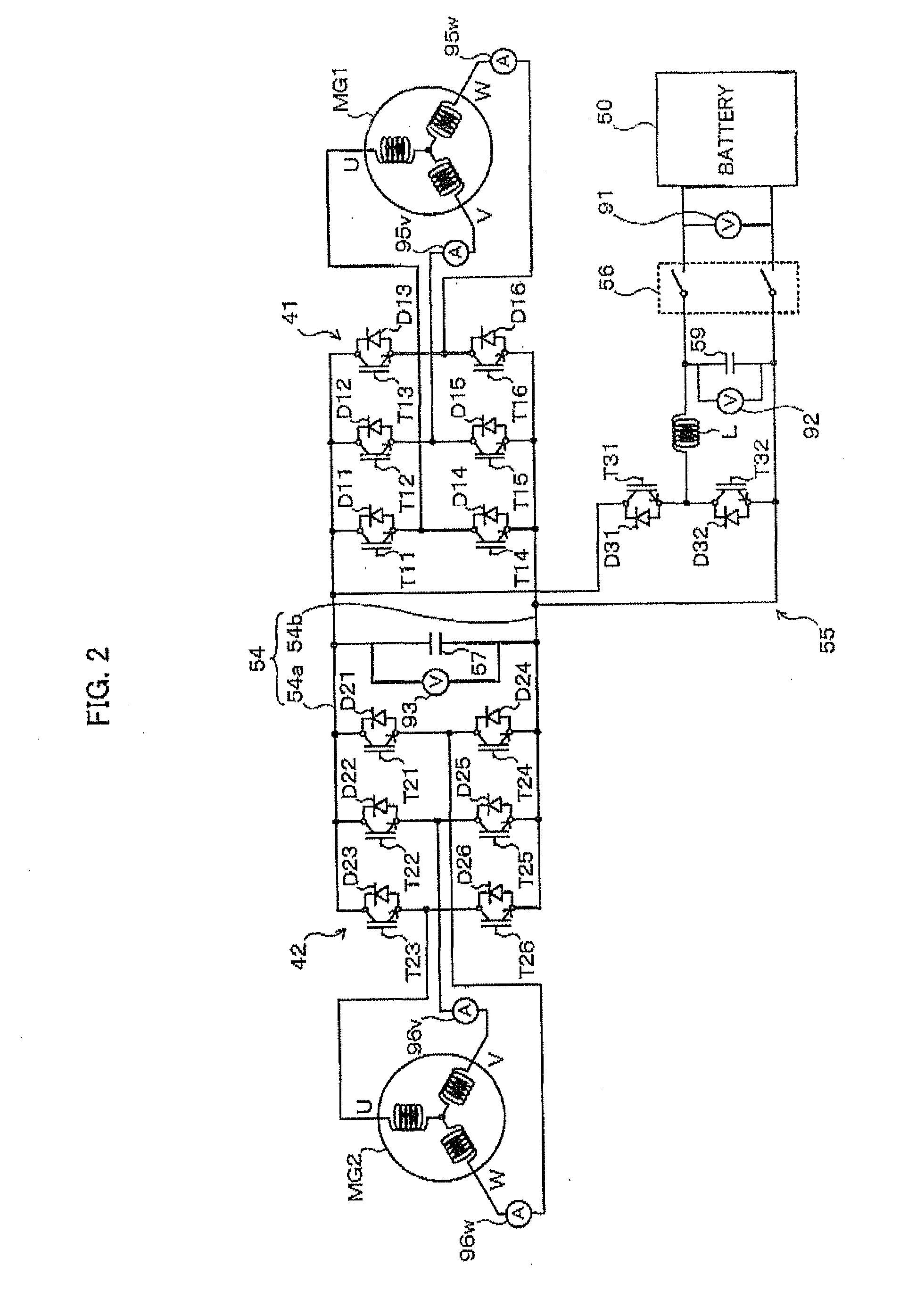
[0042]FIG. 1 is a schematic block diagram of a hybrid vehicle 20 according to an embodiment of the present invention, and FIG. 2 is a schematic block diagram of an electric drive system included in the hybrid vehicle 20. As shown in these drawings, the hybrid vehicle 20 of the embodiment includes an engine 22, a three shaft-type power distribution integration mechanism 30 connected via a damper 28 to a crankshaft 26 or an output shaft of the engine 22, a motor MG1 connected to the power distribution integration mechanism 30 and designed to have power generation capability, a reduction gear 35 connected to a ring gear shaft32a or an axle connected to the power distribution integration mechanism 30, a motor MG2 connected to the ring gear shaft 32a via the reduction gear 35, inverters 41 and 42 that convert an direct-current electric power into an alternating-Current electr...


PUM


Abstract

In the hybrid vehicle, a boost converter is controlled to make a post-boost voltage or a voltage on the side of an inverter become a target post-boost voltage corresponding to a target operation point of a motor in accordance with a target post-boost voltage setting map that divides an operation region of the motor into a non-boost region and a boost region when a operation point of the motor is included in the boost region. The target post-boost voltage setting map is prepared so that the non-boost region includes a region in which a loss produced by driving the motor when not boosting the post-boost voltages becomes smaller than the loss produced when boosting the post-boost voltage and the boost region includes a region in which the loss produced when boosting the post-boost voltage becomes smaller than the loss produced when not boosting the post-boost voltage.

Description

TECHNICAL FIELD[0001]The present invention relates to a motor drive control apparatus configured to drive and control a motor using electric power from a direct-current power source, a vehicle with the motor drive control apparatus and a motor drive control method.BACKGROUND ART[0002]Conventionally, there is known a motor drive apparatus including an inverter that drive a motor generator, a boost converter that boosts a voltage from a battery and supplies the inverter with the post-boost voltage, and a controller that provides the boost converter with a target boost voltage corresponding to a target operation state of the motor generator (for example, refer to Patent Document 1). The apparatus is provided with a map that previously defines a relationship between a torque command to the motor generator, a rotational speed of the motor generator, and the target boost voltage of the boost converter. The controller controls the boost converter so as to boost the voltage from the battery...

Claims


Application Information

Patent Timeline
Patent Type & Authority Applications(United States)
IPC IPC(8): H02P27/06B60L50/16
CPCB60K6/445B60L11/14B60L2210/14B60W10/08B60W2710/086F16H2037/0866Y02T10/70Y02T10/7077Y02T10/7225H02P23/009H02P2201/03Y02T10/642Y02T10/6239B60L50/16Y02T10/62Y02T10/64Y02T10/7072Y02T10/72
Inventor YAMAKAWA, TOSHIFUMIHANADA, HIDETOHAYASHI, KAZUHITOSUHAMA, MASAYOSHIOKAMURA, MASAKI
Owner TOYOTA JIDOSHA KK
Why Eureka
Try Eureka