Display device
a display device and display technology, applied in the field of display devices, can solve problems such as difficulty in carrying and circuit damag
- Summary
- Abstract
- Description
- Claims
- Application Information
AI Technical Summary
Benefits of technology
Problems solved by technology
Method used
Image
Examples
embodiment 1
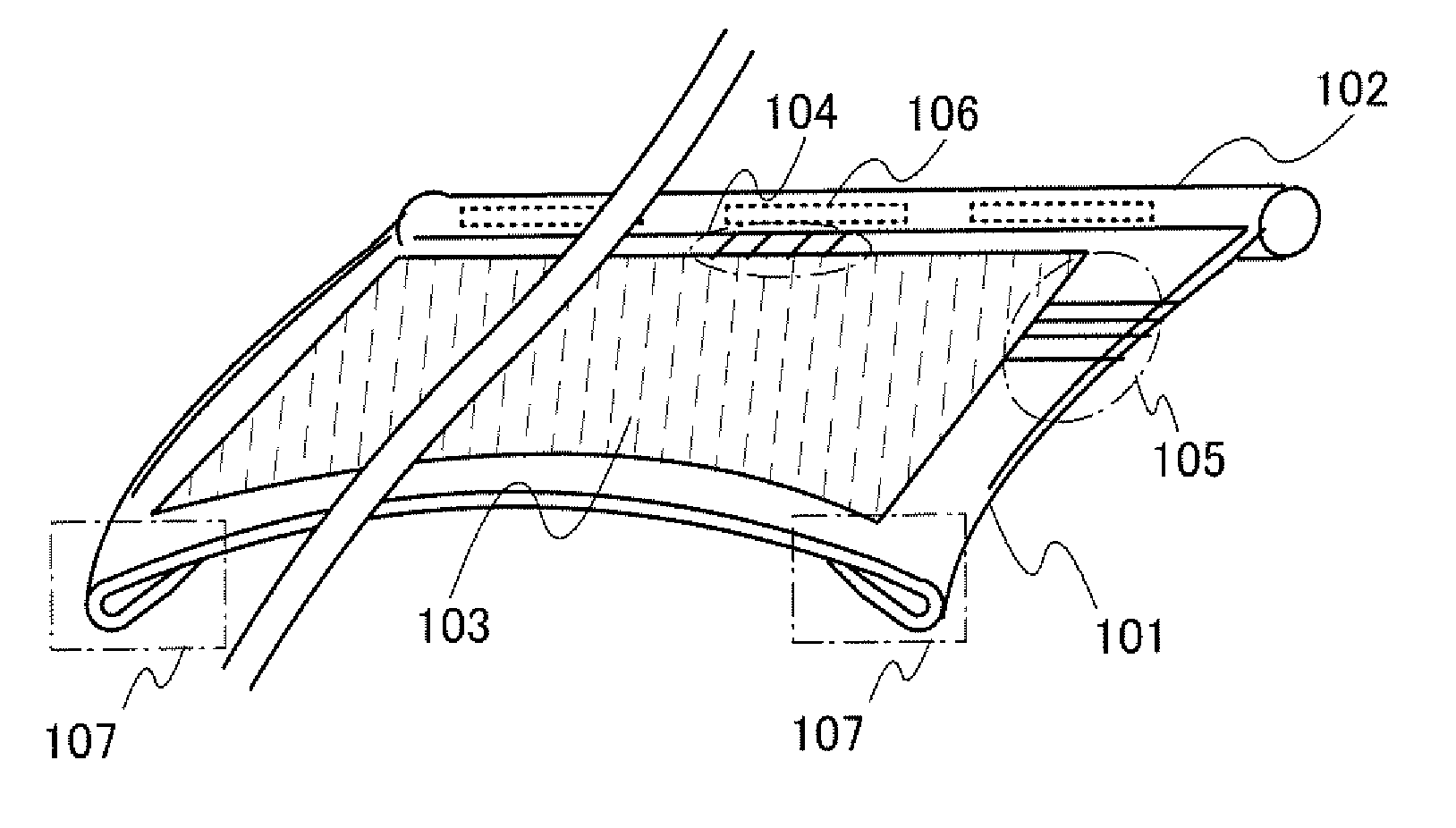
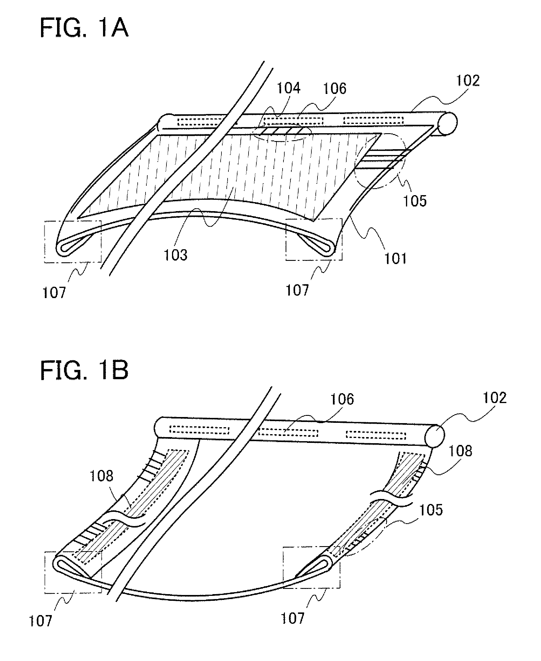
[0043]A structure disclosed in this embodiment will be schematically described with reference to FIGS. 1A and 1B and FIGS. 5A to 5C.
[0044]A display device shown in this embodiment includes an element substrate having flexibility, a display portion provided over the element substrate, a supporting portion which holds and fixes a side of the element substrate having flexibility (in a manner that prevents its movement), and a bent portion obtained by bending the element substrate. The bent portion includes a driver circuit for driving the display portion, such as a scan line driver circuit. The supporting portion includes, for example, a signal line driver circuit that outputs a signal to a signal line.
[0045]FIGS. 1A and 1B illustrate an example of the display device, which includes a supporting portion 102 provided on a side of an element substrate 101. The structure of the display device will be specifically described below with reference to FIGS. 1A and 1B. Note that FIG. 1A is a pe...
embodiment 2
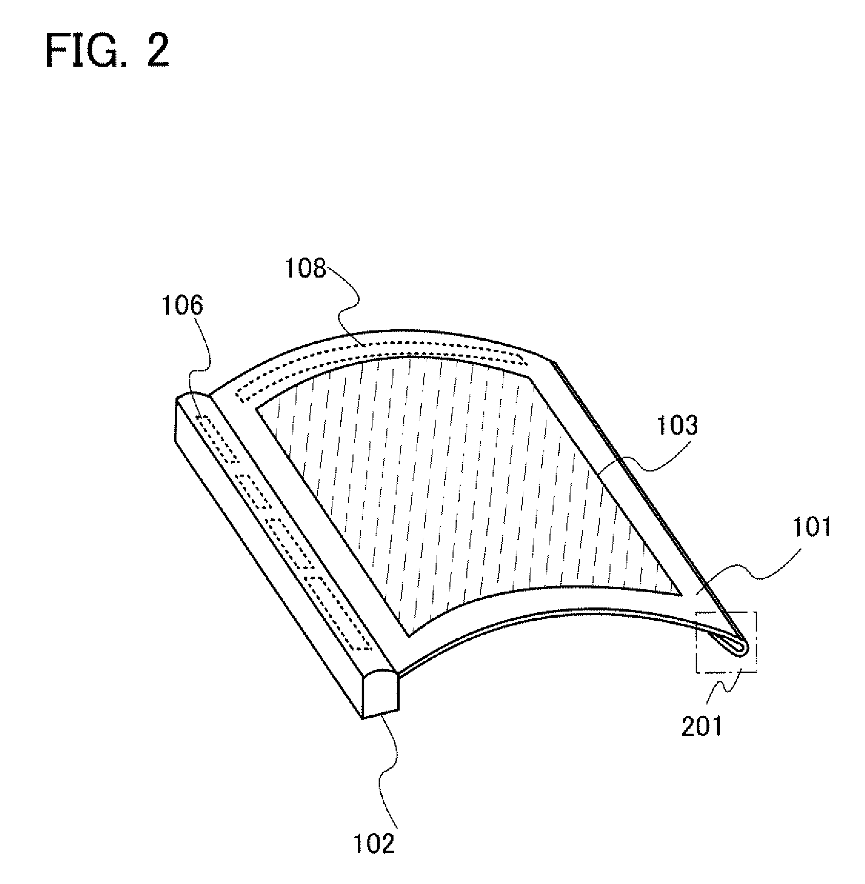
[0057]A structure different from that shown in Embodiment 1 will be described with reference to FIG. 2, FIGS. 3A to 3C, and FIGS. 4A to 4C.
[0058]In a display device of this embodiment, as illustrated in FIG. 2, a bent portion 201 is provided on a side opposite to the supporting portion 102, namely, in a direction parallel to the long axis of the supporting portion 102. In addition, as in the above embodiment, a curved portion can be formed by bending the periphery of the element substrate having flexibility, which makes it possible to reduce injury of the user caused by a slip of a finger or the like on the edge of the display device.
[0059]FIG. 3A is a top view of the display device, FIG. 3B is a cross-sectional view along line A-B of FIG. 3A, and FIG. 3C is an enlarged view of the cross section of FIG. 3B.
[0060]In the display device illustrated in FIG. 3A, a housing having a cavity is used for the supporting portion 102 and a signal line driver circuit is provided inside the housin...
embodiment 3
[0067]In this embodiment, an example of the structure of the display device will be described with reference to perspective views and cross-sectional views.
[0068]As the display device, electronic paper using an electrophoretic element as a display element, a light-emitting display device (an electroluminescence (EL) panel), a liquid crystal display device, and the like can be employed. The display device is a panel in which a display element is sealed. The panel includes a terminal electrode to which a signal is externally supplied (an external terminal electrode), and a connector, e.g., an external connecting wiring such as a flexible printed circuit (FPC), a tape automated bonding (TAB) tape, or a tape carrier package (TCP), is attached to the terminal electrode, whereby the panel is electrically connected to an external circuit including a driver circuit. An IC including the driver circuit may be directly mounted on the display device by chip on glass (COG).
[0069]An embodiment of...
PUM
| Property | Measurement | Unit |
|---|---|---|
| diameter | aaaaa | aaaaa |
| wavenumber | aaaaa | aaaaa |
| frequency | aaaaa | aaaaa |
Abstract
Description
Claims
Application Information
 - R&D
- Intellectual Property
- Life Sciences
- Materials
- Tech Scout
- Unparalleled Data Quality
- Higher Quality Content
- 60% Fewer Hallucinations
Browse by: Latest US Patents, China's latest patents, Technical Efficacy Thesaurus, Application Domain, Technology Topic, Popular Technical Reports.
© 2025 PatSnap. All rights reserved.Legal|Privacy policy|Modern Slavery Act Transparency Statement|Sitemap|About US| Contact US: help@patsnap.com


