Magnetic sensor with perpendicular anisotrophy free layer and side shields

Active Publication Date: 2011-01-13
SEAGATE TECH LLC
View PDF12 Cites 66 Cited by
  • Summary
  • Abstract
  • Description
  • Claims
  • Application Information

AI Technical Summary

Benefits of technology

The present disclosure relates to a magnetic sensor with a perpendicular anisotropy free layer and side shields.

Problems solved by technology

In addition, changes in the canting direction caused by thermal variations or external fields may increase noise and instability in the sensor.
Furthermore, when a permanent magnet is emplo

Method used


Image

  • Magnetic sensor with perpendicular anisotrophy free layer and side shields
  • Magnetic sensor with perpendicular anisotrophy free layer and side shields
  • Magnetic sensor with perpendicular anisotrophy free layer and side shields

Examples


Embodiment Construction

In the following description, reference is made to the accompanying set of drawings that form a part hereof and in which are shown by way of illustration several specific embodiments. It is to be understood that other embodiments are contemplated and may be made without departing from the scope or spirit of the present disclosure. The following detailed description, therefore, is not to be taken in a limiting sense. The definitions provided herein are to facilitate understanding of certain terms used frequently herein and are not meant to limit the scope of the present disclosure.

Unless otherwise indicated, all numbers expressing feature sizes, amounts, and physical properties used in the specification and claims are to be understood as being modified in all instances by the term “about.” Accordingly, unless indicated to the contrary, the numerical parameters set forth in the foregoing specification and attached claims are approximations that can vary depending upon the desired prop...


PUM


Abstract

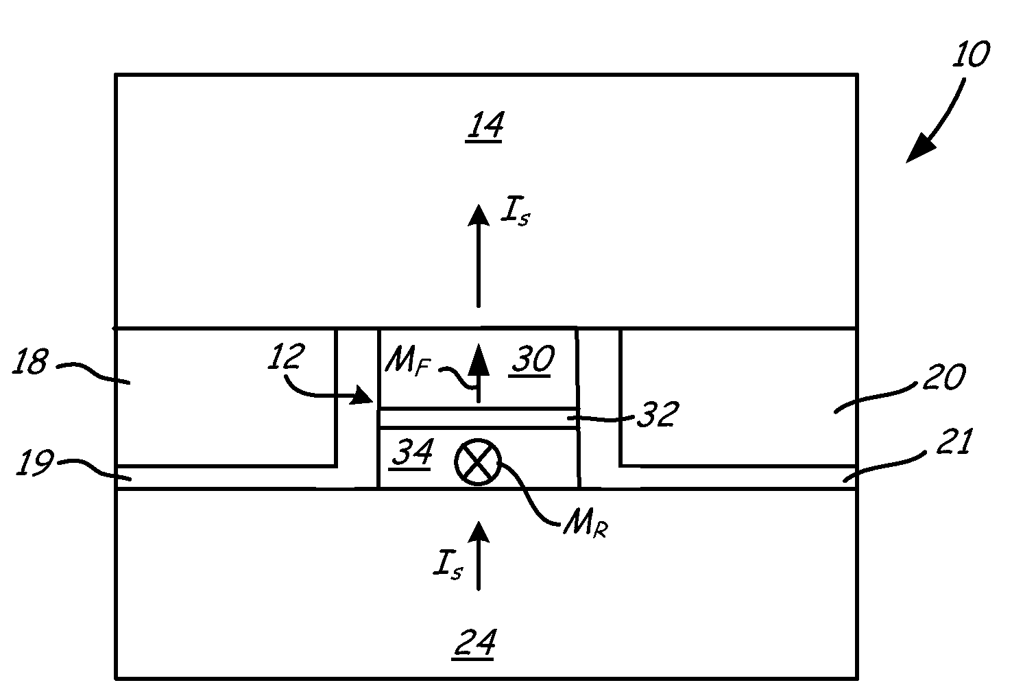
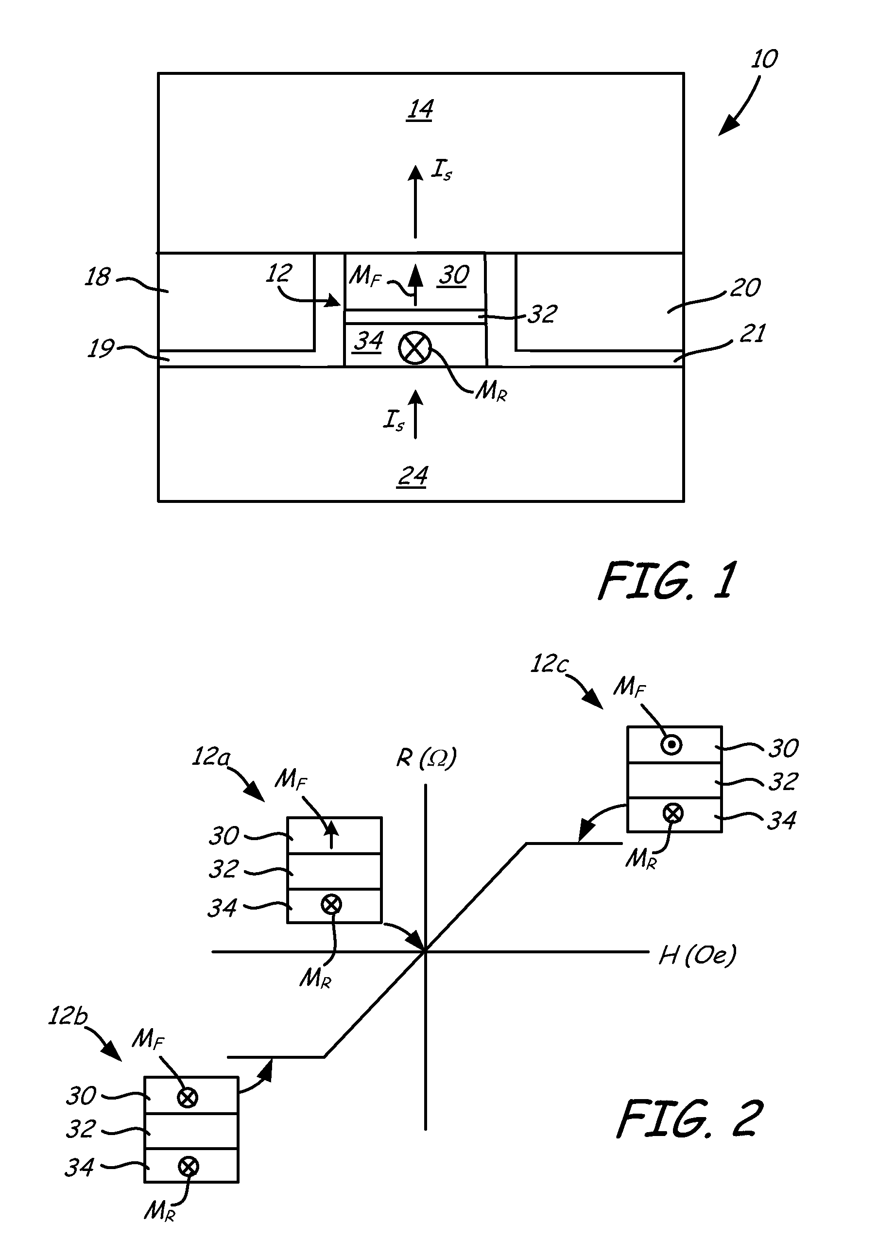
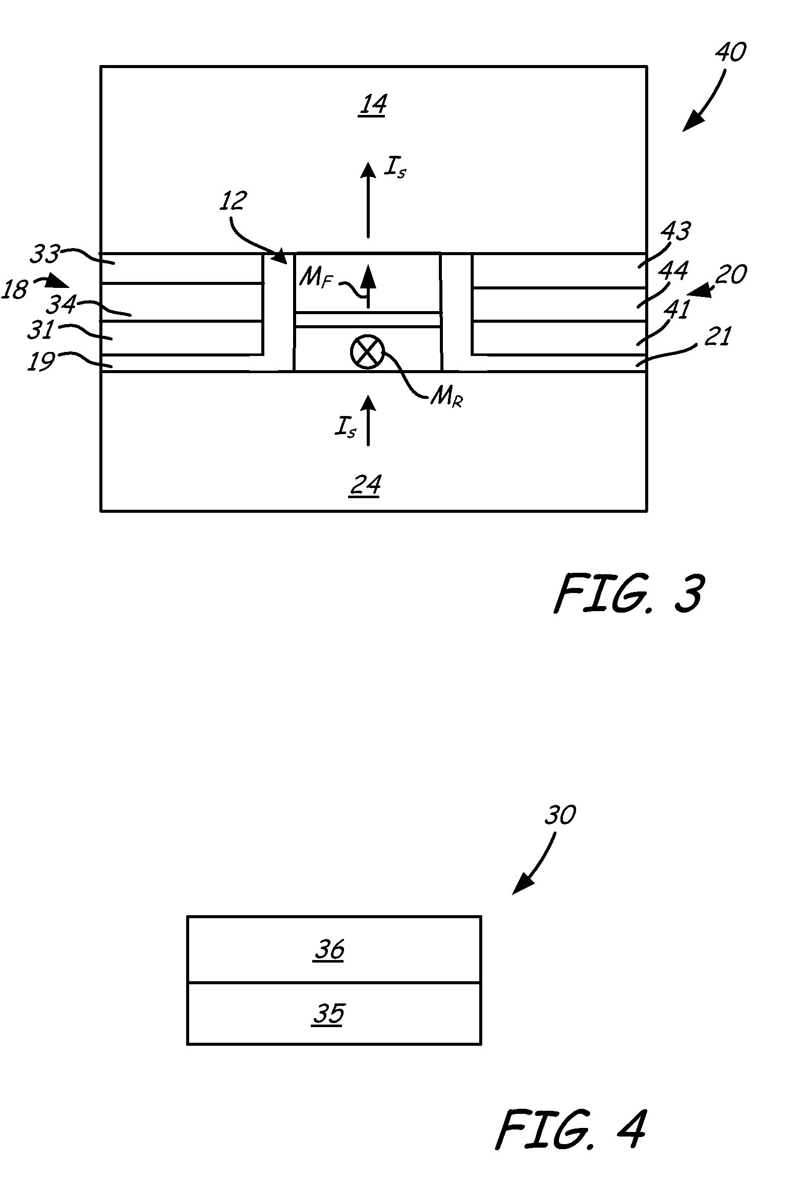
A tunneling magneto-resistive reader includes a sensor stack separating a top magnetic shield from a bottom magnetic shield. The sensor stack includes a reference magnetic element having a reference magnetization orientation direction and a free magnetic element having a free magnetization orientation direction substantially perpendicular to the reference magnetization orientation direction. A non-magnetic spacer layer separates the reference magnetic element from the free magnetic element. A first side magnetic shield and a second side magnetic shield is disposed between the top magnetic shield from a bottom magnetic shield, and the sensor stack is between the first side magnetic shield and the second side magnetic shield. The first side magnetic shield and the second side magnetic shield electrically insulates the top magnetic shield from a bottom magnetic shield.

Description

BACKGROUNDIn an electronic data storage and retrieval system, a magnetic recording head can include a reader portion having a sensor for retrieving magnetically encoded information stored on a magnetic medium. Magnetic flux from the surface of the medium causes rotation of the magnetization vector of a sensing layer or layers of the sensor, which in turn causes a change in the electrical properties of the sensor. The sensing layers are often called free layers, since the magnetization vectors of the sensing layers are free to rotate in response to external magnetic flux. The change in the electrical properties of the sensor may be detected by passing a current through the sensor and measuring a voltage across the sensor. Depending on the geometry of the device, the sense current may be passed in the plane (CIP) of the layers of the device or perpendicular to the plane (CPP) of the layers of the device. External circuitry then converts the voltage information into an appropriate form...

Claims


Application Information

Patent Timeline
IPC IPC(8): G11B5/127
CPCG01R33/098H01L43/08G11B5/398G11B5/3912H10N50/10
Inventor DIMITROV, DIMITAR V.GAO, ZHENGJUNG, WONJOONANDERSON, PAUL EDWARDHEINONEN, OLLE GUNNAR
Owner SEAGATE TECH LLC
Why Eureka
Try Eureka