Relay device, communication system, and communication method

Inactive Publication Date: 2011-01-13
SHARP KK
View PDF9 Cites 7 Cited by
  • Summary
  • Abstract
  • Description
  • Claims
  • Application Information

AI Technical Summary

Benefits of technology

[0031]According to the present invention, on an uplink of the communication system including the terminal, the relay device, and the base station, the degradation of transmission characteristics can be suppressed as much as possible even when the terminal has an amplifier with a relatively narrow linear region, by transmitting a single-carrie

Problems solved by technology

A multi-carrier signal, however, has a high PAPR (Peak-to-Average Power Ratio), and hence nonlinearity of an amplifier becomes a problem.
The next generation mobile communication is very

Method used


Image

  • Relay device, communication system, and communication method
  • Relay device, communication system, and communication method
  • Relay device, communication system, and communication method

Examples


first embodiment

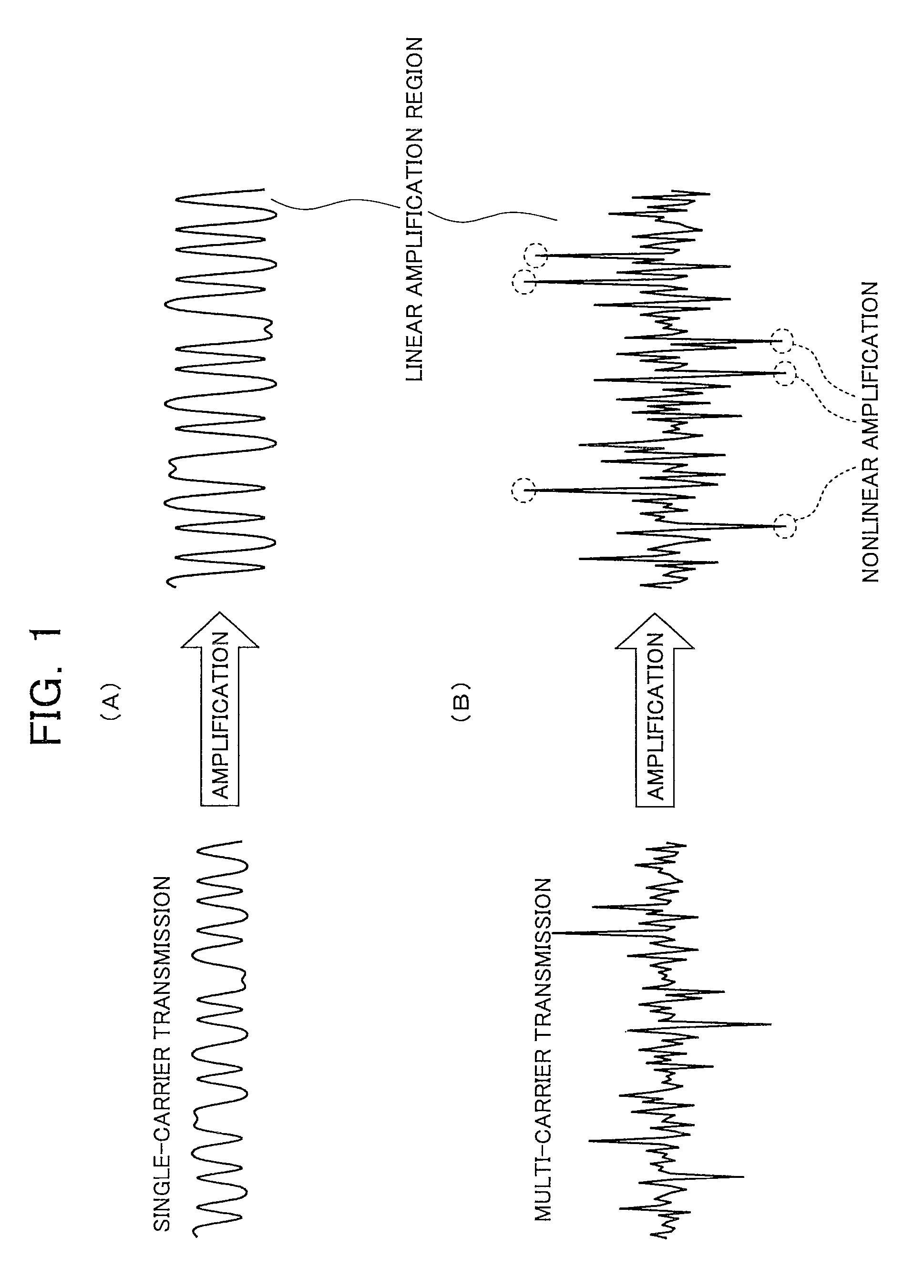
[0051]FIG. 1 is a diagram for comparison of a single-carrier signal waveform with a multi-carrier signal waveform. FIG. 1(A) is a waveform diagram of a single-carrier signal and FIG. 1(B) is a waveform diagram of a multi-carrier signal.

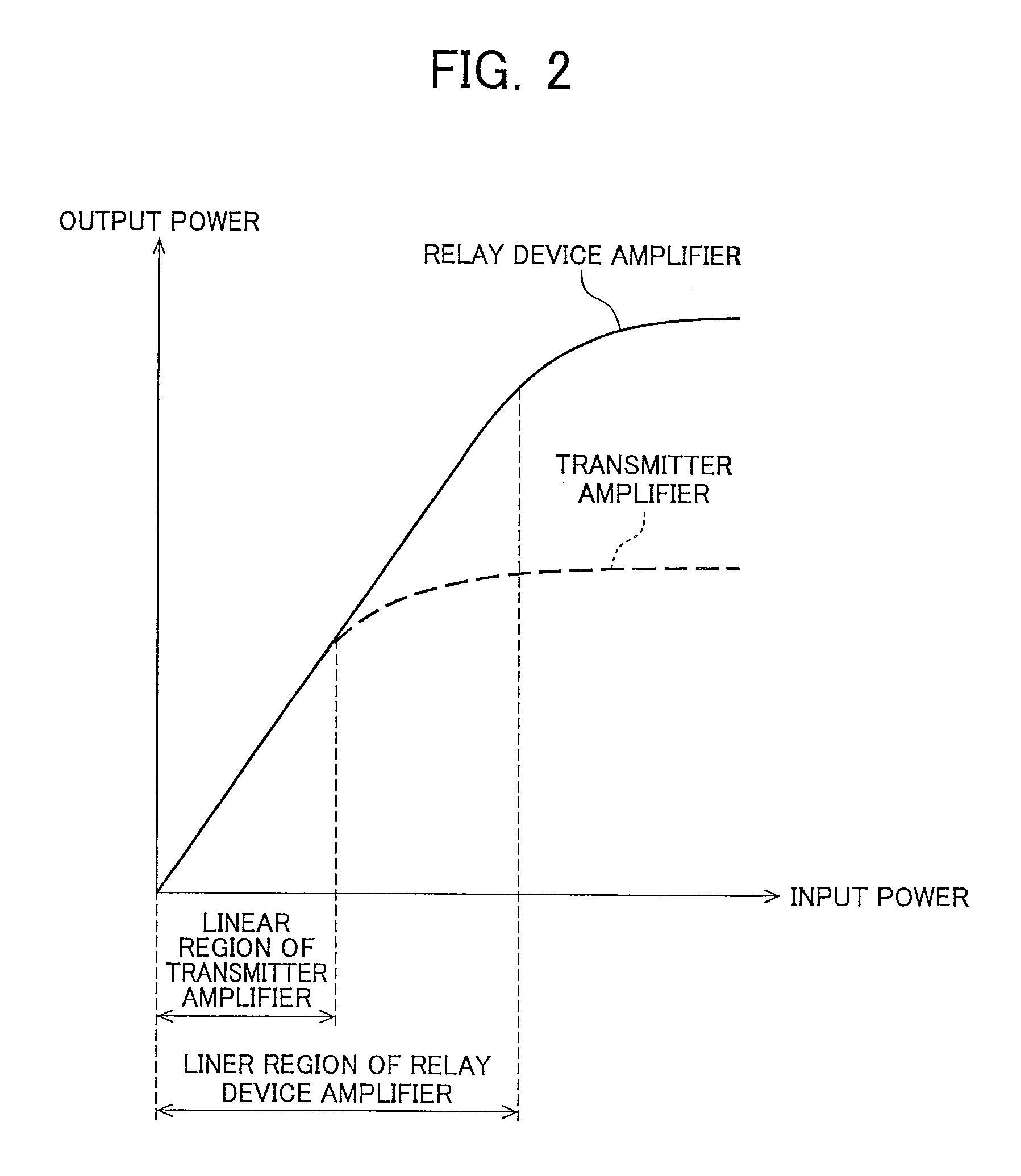
[0052]In a multi-carrier transmission such as OFDM and MC-CDMA, independently modulated carriers are superimposed, so that PAPR becomes higher as the number of subcarriers increases. Therefore, in case of using an amplifier with a narrow linear amplification region, the single-carrier signal can be amplified without any distortion as shown in FIG. 1(A), whereas the multi-carrier signal becomes distorted since the signals beyond the linearly amplifiable region cannot be linearly amplified as depicted by broken line circles of FIG. 1(B).

[0053]Transmission of signals distorted by the amplifier leads to a degradation of transmission characteristics. Use of an amplifier with a wider linear region therefor results in an increase in the size and cost of a te...

second embodiment

[0071]Although the above description of the first embodiment has been made of a case where the relay station 1 performs no bit demodulation, the configuration that the relay station performs a symbol-to-bit demodulation may be employed. In this embodiment, a configuration example will be described of a communication system performing the symbol-to-bit demodulation and generating and transmitting a symbol replica.

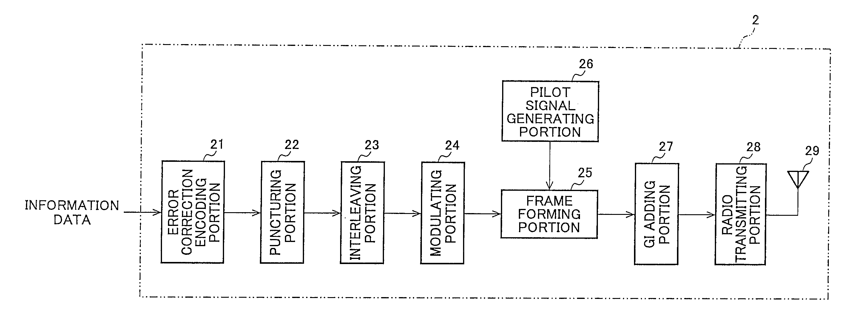
[0072]FIG. 10 is a block diagram of a configuration example of the relay station 1 according to the second embodiment of the present invention. In the diagram, the relay station 1 includes the antennas 11 and 15, the single-carrier signal receiving portion 12, a converting portion 16, and the multi-carrier signal transmitting portion 14. The single-carrier signal transmitting portion 12 includes the radio receiving portion 121, the GI removing portion 122, the DFT portion 123, the pilot signal extracting portion 124, the equalizing portion 125, the weight calculating portion...

third embodiment

[0080]In a case where the channel environment is poor between the relay station and the base station, the configuration that the relay station performs the error correction decoding process may be employed. Description of this embodiment will be made of a configuration example of the communication system in which the relay station carries out the error correction decoding.

[0081]FIG. 14 is a block diagram of a configuration example of the relay station according to a third embodiment of the present invention. In the diagram, the relay station 1 includes the antennas 11 and 15, the single-carrier signal receiving portion 12, a converting portion 17, and the multi-carrier signal transmitting portion 14. The single-carrier signal receiving portion 12 includes the radio receiving portion 121, the GI removing portion 122, the DFT portion 123, the pilot signal extracting portion 124, the equalizing portion 125, the weight calculating portion 126, and the IDFT portion 127. The multi-carrier...


PUM


Abstract

Even when an amplifier has a comparatively narrow linear region in a terminal, it is possible to suppress degradation of the transmission characteristic by using single-carrier transmission between the terminal and a relay device while using multi-carrier transmission between the relay device and a base station on an uplink of a communication system. The relay station (1) includes: a single-carrier signal receiving portion (12) which receives a single-carrier signal from the terminal and performs signal processing; a converting portion (13) which converts a time region symbol output from the single-carrier signal receiving portion (12) into a frequency domain symbol; and a multi-carrier signal transmitting portion (14) which makes the symbol converted by the converting portion (13) to be a multi-carrier signal and transmits the multi-carrier signal to the base station.

Description

TECHNICAL FIELD[0001]The present invention relates to a relay device, a communication system, and a communication method and to a relay device converting a single-carrier signal from a terminal into a multi-carrier signal for output, a communication system having the relay device, and a communication method.BACKGROUND OF THE INVENTION[0002]Recently, a multi-carrier transmission such as OFDM (Orthogonal Frequency Division Multiplexing) or MC-CDMA (Multi-Carrier Code Division Multiple Access) ensuring good transmission characteristics even in the multi-path environment through a parallel transmission of a multiplicity of orthogonal narrow-band carriers has attracted attention in the radio communication.[0003]A multi-carrier signal, however, has a high PAPR (Peak-to-Average Power Ratio), and hence nonlinearity of an amplifier becomes a problem. A single-carrier transmission, on the other hand, is becoming an attractive transmission technique for uplink (transmission from a terminal to ...

Claims


Application Information

Patent Timeline
IPC IPC(8): H04B7/14
CPCH04B7/15542H04B7/2606H04L5/0007H04L5/0028H04L25/0228H04L2025/03414H04L25/067H04L25/20H04L27/2614H04L27/36H04L25/03159
Inventor NAKAMURA, OSAMUNOGAMI, TOSHIZOYAMADA, RYOTA
Owner SHARP KK
Why Eureka
Try Eureka