Blood pressure information measurement device

a technology of information measurement and blood pressure, which is applied in the field of blood pressure information measurement devices, can solve the problems of inability to reliably wind the cuff around the measurement site, the device is necessarily increased in size, and the measurement posture is limited to a specific posture. it can achieve the effect of avoiding usability

Inactive Publication Date: 2011-01-13
OMRON HEALTHCARE CO LTD
View PDF5 Cites 27 Cited by
  • Summary
  • Abstract
  • Description
  • Claims
  • Application Information

AI Technical Summary

Benefits of technology

[0013]Therefore, in view of solving the above problems, preferred embodiments of the present invention provide a cuff of a sphygmomanometer that is easily attached to a measurement site and in which the cuff and a main body are separated from each other, and reliable winding of the cuff around the measurement site is easily repeated in every measurement.
[0023]According to a preferred embodiment of the present invention, in the sphygmomanometer in which the cuff and the main body are separated from each other, the cuff can be easily attached to the measurement site, and reliable winding of the cuff around the measurement site can be repeated in every measurement. Therefore, the blood pressure information measurement device has favorable usability while being capable of precisely and stably measuring the blood pressure information.

Problems solved by technology

On the other hand, in the sphygmomanometer in which the cuff and the main body are integrated, there are problems including a problem that the device is necessarily increased in size and a problem that a measurement posture is limited to a specific posture.
Thus, reliable winding of the cuff around the measurement site is not always repeated in every measurement.
However, in the cuff accommodating the curler, there is a problem that a winding task thereof is troublesome in comparison to the above sphygmomanometer in which the cuff and the main body are integrated.
This pushing and extending task is a cause of problems.
Thus, there is a fear that a sufficient bias force is not obtained.
However, in that case, since a force required for an operation of an operation unit becomes larger, there is a problem that operability is lowered.
Since configurations of the above-described power transmission mechanism and the like are complicated, there is also a problem that the power transmission mechanism is easily broken due to repetitive use.

Method used


Image

  • Blood pressure information measurement device
  • Blood pressure information measurement device
  • Blood pressure information measurement device

Examples


first preferred embodiment

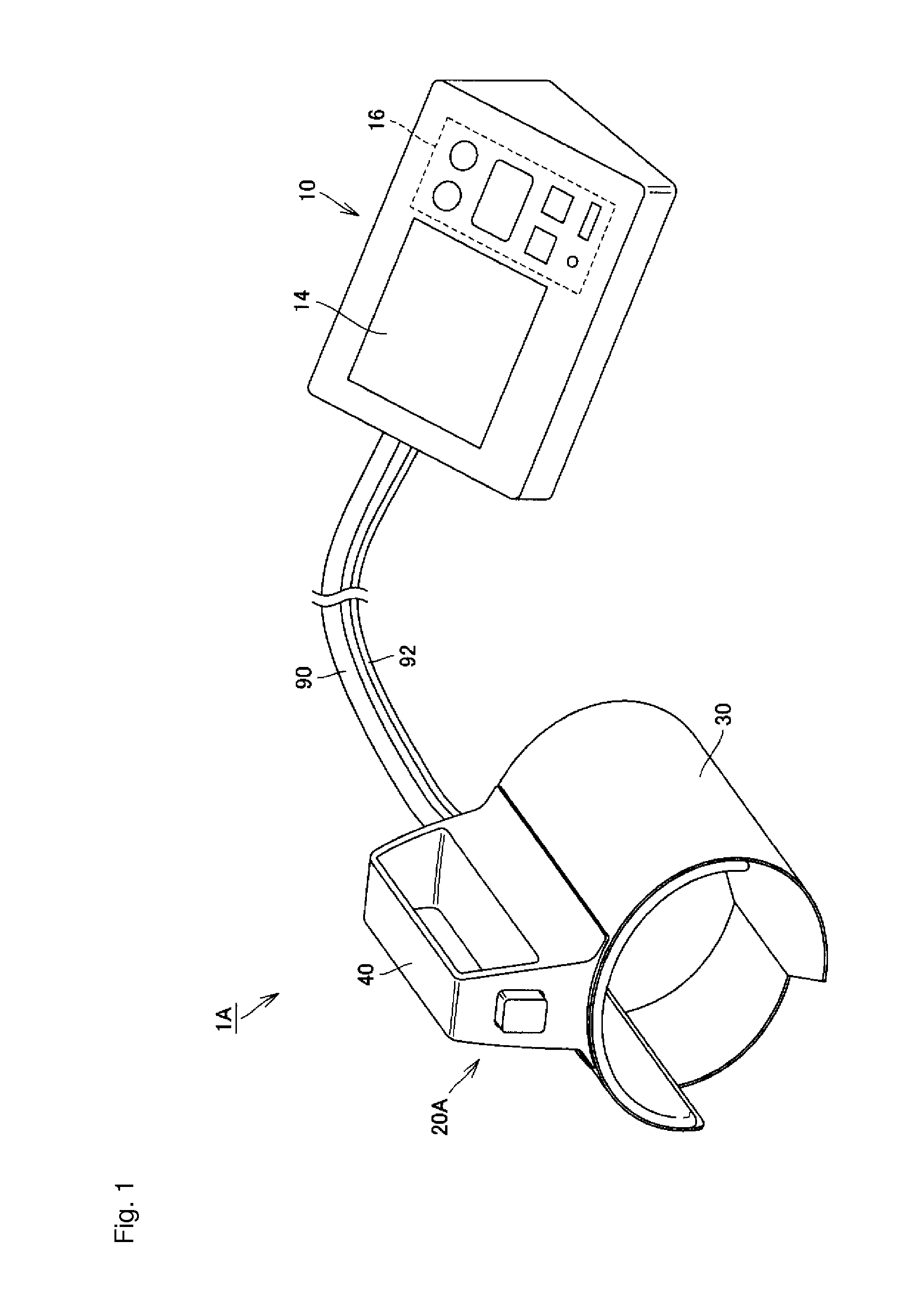
[0038]FIG. 1 is a view showing an outer appearance structure of a sphygmomanometer according to a first preferred embodiment of the present invention. Firstly, with reference to FIG. 1, the outer appearance structure of a sphygmomanometer 1A according to the present preferred embodiment will be described.

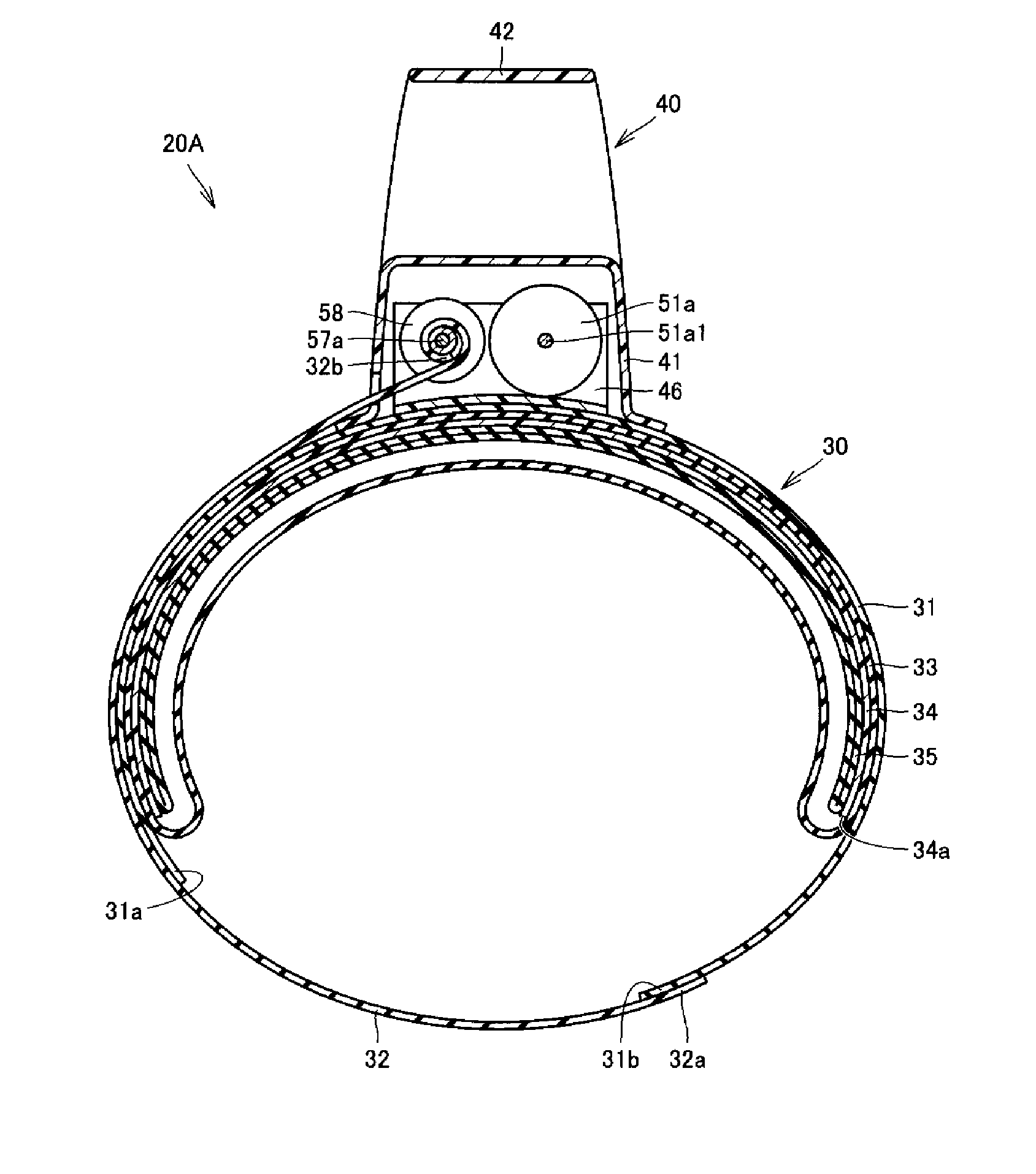
[0039]As shown in FIG. 1, the sphygmomanometer 1A according to the present preferred embodiment is provided with a main body 10, a cuff 20A, an air tube 90, and a connection cable 92. The main body 10 has a box shaped casing, and a display unit 14 and an operation unit 16 are provided on an upper surface thereof. The main body 10 is mounted on a surface of a table or the like to be used at a time of measurement. The cuff 20A has a tubular cuff main body portion 30 including a hollow opening portion into which an upper arm is insertable in the axial direction, and a gripping portion 40 provided on an outer peripheral surface of this cuff main body portion 30. The cuff 20A is attached...

second preferred embodiment

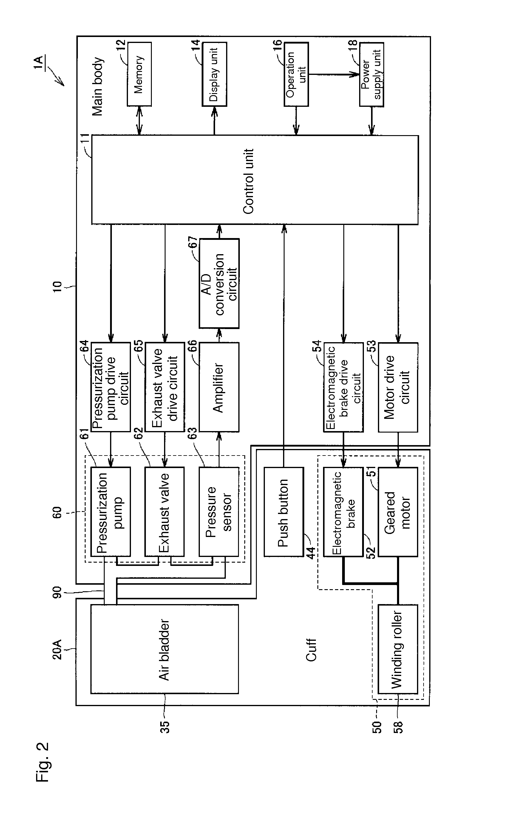
[0084]FIG. 10 is a functional block configuration diagram of a sphygmomanometer according to a second preferred embodiment of the present invention. Firstly, with reference to FIG. 10, a functional block configuration of a sphygmomanometer 1B according to the present preferred embodiment will be described. It should be noted that the sphygmomanometer 1B according to the present preferred embodiment is the same as the sphygmomanometer 1A according to the first preferred embodiment in terms of an outer appearance structure, and major components of the functional block configuration thereof are also common to the first preferred embodiment. Therefore, the same reference numerals are given to similar components to the first preferred embodiment in the figures, and the description thereof will not be repeated.

[0085]In the sphygmomanometer 1A according to the first preferred embodiment, the air bladder 35 and the air system component 60 preferably are utilized as the tightening force dete...


PUM


Abstract

A sphygmomanometer separately includes a cuff accommodating an air bladder and a main body provided with an expanding / contracting mechanism arranged to expand and contract the air bladder, and the cuff includes a tubular cuff main body portion into which an upper arm is insertable and a gripping portion provided on an outer peripheral surface of the cuff main body portion. The cuff main body portion has a tightening belt wrapped around the outer side of the air bladder and a tightening length adjustment mechanism arranged to variably adjust a tightening length of the tightening belt over the upper arm. The tightening length adjustment mechanism includes a winding roller arranged to wind and feed the tightening belt, a geared motor arranged to drive and rotate the winding roller, and an electromagnetic brake arranged to apply a braking force to the winding roller. With such a configuration, in the sphygmomanometer in which the cuff and the main body are separated from each other, the cuff can be easily attached to a measurement site, and reliable winding of the cuff around the measurement site can be repeated in every measurement.

Description

BACKGROUND OF THE INVENTION[0001]1. Field of the Invention[0002]The present invention relates to a blood pressure information measurement device capable of measuring blood pressure information such as a blood pressure value, and more particularly to a blood pressure information measurement device separately including a cuff attached to a measurement site to be used, and a main body mounted on a surface to be used.[0003]2. Description of the Related Art[0004]Acquiring blood pressure information of a subject is highly important in terms of knowing a health condition of the subject. In recent years, it is not limited to acquiring a systolic blood pressure value (a maximum blood pressure value), a diastolic blood pressure value (a minimum blood pressure value), and the like, whose effectiveness has been widely recognized as a representative index of health management from the conventional art, and attempts have been made in capturing a change in a heart load and hardness of an artery by...

Claims


Application Information

Patent Timeline
Patent Type & Authority Applications(United States)
IPC IPC(8): A61B5/022
CPCA61B5/02233A61B5/02141
Inventor SANO, YOSHIHIKOUESAKA, CHISATOARIGA, HIROYASU
Owner OMRON HEALTHCARE CO LTD
Why Eureka
Try Eureka