Device for controlling quantity of injected fuel

Active Publication Date: 2011-01-13
DENSO CORP
View PDF3 Cites 12 Cited by
  • Summary
  • Abstract
  • Description
  • Claims
  • Application Information

AI Technical Summary

Benefits of technology

[0021]Accordingly, the device can prevent the valve closing operation start time from being determined from the fuel pressure detected during the fuel injection, and the device can control a quantity of the injected fuel with high precision.
[0022]Further, no analog-to-digital conversion of the signal is performed in the second process routine. Therefore, the execution period of the second process routine can be shortened. In this case, even when

Problems solved by technology

In this case, there is a high probability that an execution period of time required of the interruption process to set the on-timing and the off-timing in the timer for the present fuel injection overlaps with a fuel injection period of the preceding fuel injection.
This means that the

Method used


Image

  • Device for controlling quantity of injected fuel
  • Device for controlling quantity of injected fuel
  • Device for controlling quantity of injected fuel

Examples


Example

First Embodiment

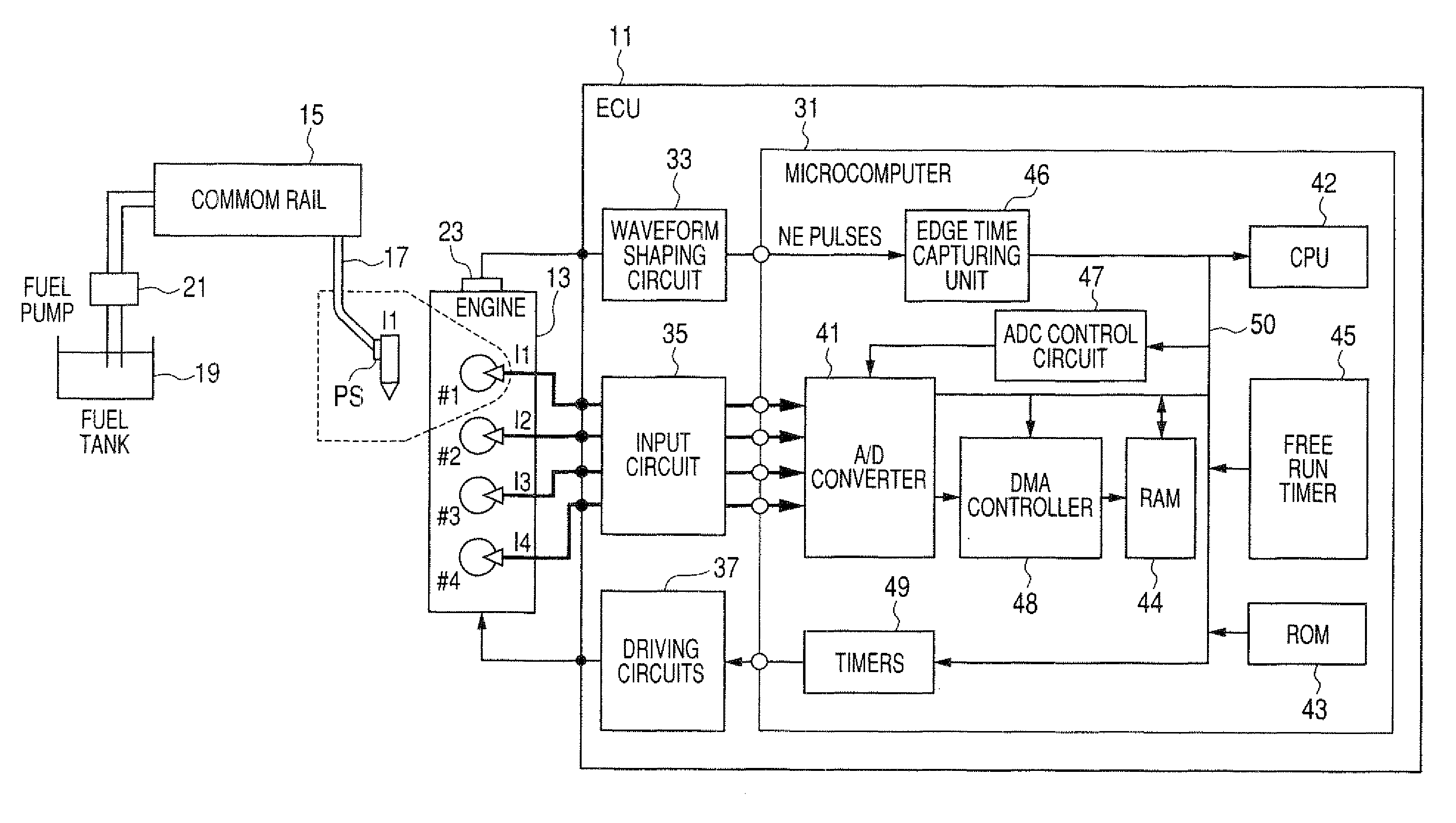
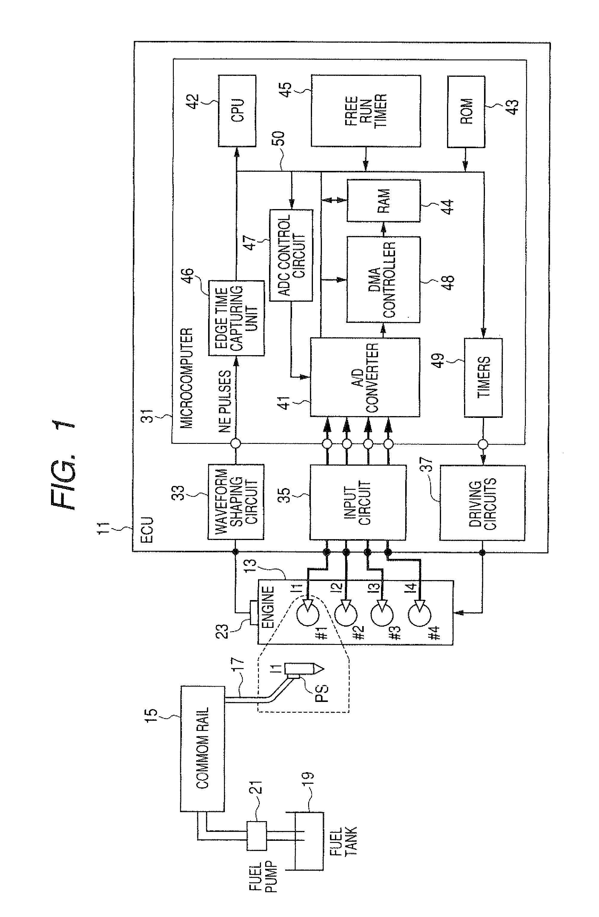
[0035]FIG. 1 is a block diagram of a fuel injection control device according to the first embodiment. As shown in FIG. 1, four fuel injection valves (hereinafter called injectors) I1, I2, I3 and I4 are located on an on-board diesel engine 13 of a vehicle so as to inject fuel into four cylinders #1, #2, #3 and #4 of the engine 13, respectively. An electronic control unit (ECU) 11 representing a fuel injection control device controls each injector Ij (j=1, 2, 3 or 4) to inject fuel into the engine 13 by a required quantity. Each injector Ij is formed of an electromagnetic valve. When electric current is supplied to a coil of the injector Ij, the injector Ij is opened.

[0036]Fuel held in a fuel tank 19 of the vehicle is pumped up by a fuel pump 21 and is supplied to a common rail 15 acting as an accumulated pressure chamber of the fuel. The fuel pump 21 is formed of an engine-driven type of high-pressure pump. This pump 21 is driven by the rotational force of a crankshaf...

Example

Second Embodiment

[0099]In this embodiment, the ECU 11 controls a quantity of the fuel injected into the cylinder #x of the engine 13 in the repeating timer trigger A / D conversion mode. That is, the ECU 11 according to the second embodiment differs from the ECU 11 according to the first embodiment in that the A / D conversion in the A / D converter 41 is repeatedly performed to perform one fuel injection into one cylinder #x.

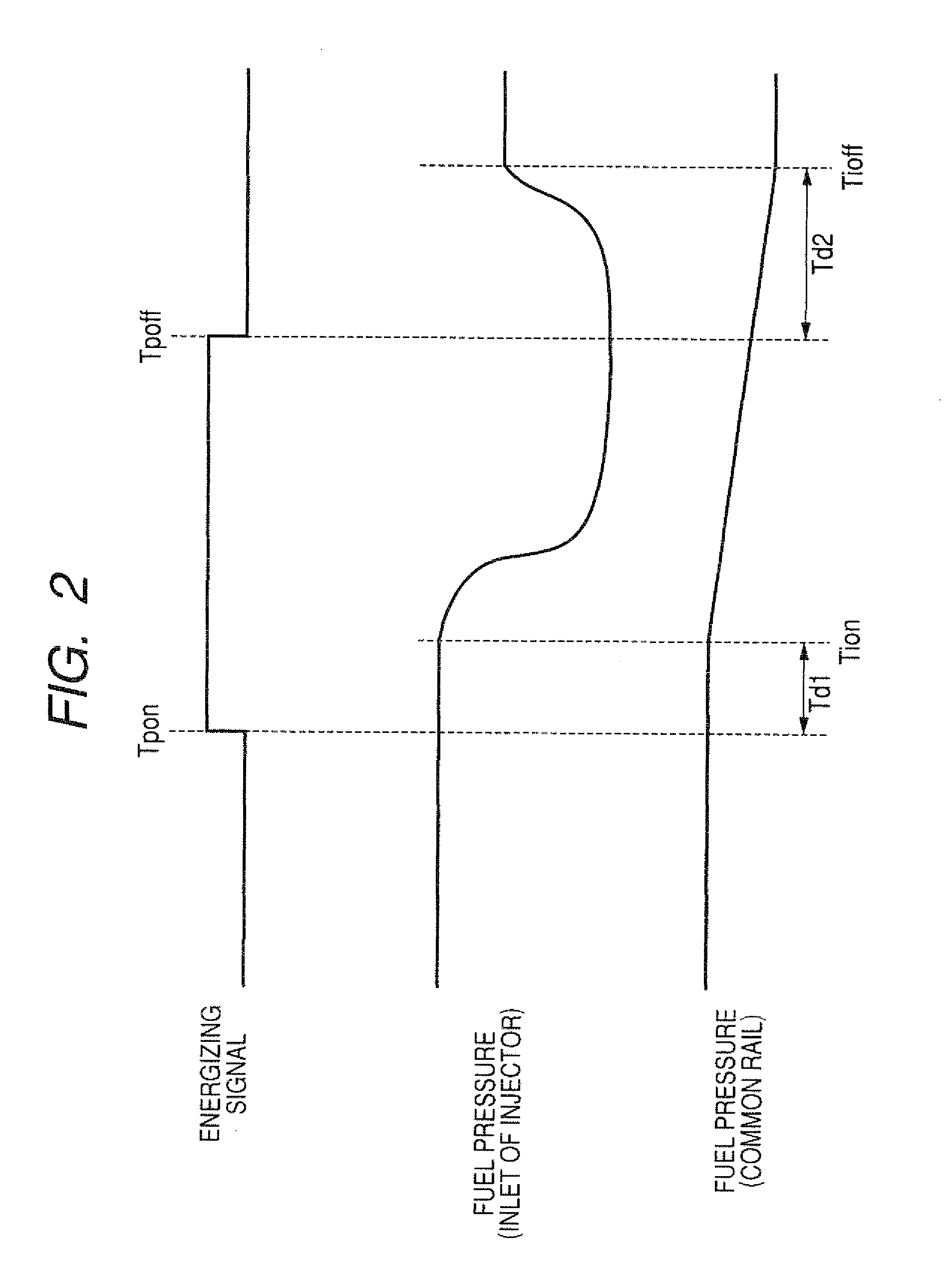
[0100]The CPU 42 initially performs an NE pulse interruption process to determine the opening start time Tpon (i.e., the on time of the energizing signal) and a plurality of A / D conversion times. After the completion of the NE pulse interruption process, the CPU 42 performs an injection end setting interruption process to determine the closing start time Tpoff (i.e., the off time of the energizing signal).

[0101]FIG. 6 is a flow chart showing the NE pulse interruption process ac cording to the second embodiment, while FIG. 7 is a flow chart showing the injection end s...

Example

Third Embodiment

[0137]In this embodiment, each of the injectors I1 to I4 performs a short-term injection. That is, each injector performs the injection in a short injection period of time. In the case of this short-term injection, when the injection end setting interruption process is performed in response to a request generated at the opening start time Tpon, an injection period of time determined in this interruption process is too short to set the closing start time Tpoff, determined in the CPU 42, in the timer 49 before the closing start time Tpoff. Therefore, assuming that the NE pulse interruption process shown in FIG. 3 is performed in the case of the short-term injection to output an injection end setting interruption request at the opening start time Tpon, the CPU 42 cannot set the closing start time Tpoff in the timer 49 before the closing start time Tpoff.

[0138]To reliably set the closing start time Tpoff in the timer 49 before the closing start time Tpoff in the case of ...


PUM


Abstract

A control device has a CPU for determining an opening time and a conversion time, set in a non-injection period between preceding and present injections, in an interception process every fuel injection, and a control circuit for controlling a converting unit, independent of the operation of the CPU, to convert an analog signal, indicating fuel pressure of an injector, into a converted value at the conversion time. The CPU determines a closing time from the opening time and the converted value in another interception process. The device has a driving circuit for starting the valve opening at the opening time to open the injector and to inject fuel from the opened injector into an engine and starting the valve closing at the closing time to close the injector and to stop the fuel injection when the injected fuel reaches a required quantity.

Description

CROSS-REFERENCE TO RELATED APPLICATION[0001]This application is based upon and claims the benefit of priority of the prior Japanese Patent Application 2009-154715 filed on Jul. 13, 2009, so that the contents of which are incorporated herein by reference.BACKGROUND OF THE INVENTION[0002]1. Field of the Invention[0003]The present invention relates to a fuel injection control device which controls a quantity of the fuel injected from a fuel injection valve into an internal combustion engine by adjusting an opening period of the fuel injection valve.[0004]2. Description of Related Art[0005]A fuel injection control device is mounted on a vehicle to control the injected fuel, actually injected from a fuel injection valve into an internal combustion engine, at a required quantity determined based on operating states of the engine. To control the injected fuel at the required quantity, it is required to determine a fuel injection period of time (i.e., an opening period of the valve). Howeve...

Claims


Application Information

Patent Timeline
IPC IPC(8): F02D41/30
CPCF02D41/2425F02D41/3005Y02T10/44F02D41/3836F02D41/401F02D41/34Y02T10/40
Inventor KANEKO, MASAYUKINAKAGAWA, HIRONARITOJO, SHIGEOYABE, MITSUHIRO
Owner DENSO CORP
Why Eureka
Try Eureka