Process For The Production Of Carbon Dioxide Utilizing A Co-Purge Pressure Swing Adsorption Unit

a technology of adsorption unit and adsorption unit, which is applied in the direction of liquefaction, separation process, lighting and heating apparatus, etc., can solve the problems of high process operation cost, high energy and maintenance cost, and large investment of the process utilized for this recovery

Active Publication Date: 2011-01-20
LAIR LIQUIDE SA POUR LETUDE & LEXPLOITATION DES PROCEDES GEORGES CLAUDE
View PDF22 Cites 85 Cited by
  • Summary
  • Abstract
  • Description
  • Claims
  • Application Information

AI Technical Summary

Problems solved by technology

Accordingly, the processes utilized for this recovery require a large investment due to equipment costs and also high regeneration energy requirements.
The process requires operation at high pressure and cold temperature though.
Therefore, while it may be appropriate to use the CO2 CPU process in a very large scale CO2 recovery plant (>1000 TPD), when applying the CO2 CPU process in a small size CO2 recovery plant (typically 100 to 500 TPD merchant CO2 plants), the energy and maintenance costs are considered to be usually high.

Method used


Image

  • Process For The Production Of Carbon Dioxide Utilizing A Co-Purge Pressure Swing Adsorption Unit
  • Process For The Production Of Carbon Dioxide Utilizing A Co-Purge Pressure Swing Adsorption Unit
  • Process For The Production Of Carbon Dioxide Utilizing A Co-Purge Pressure Swing Adsorption Unit

Examples


first embodiment

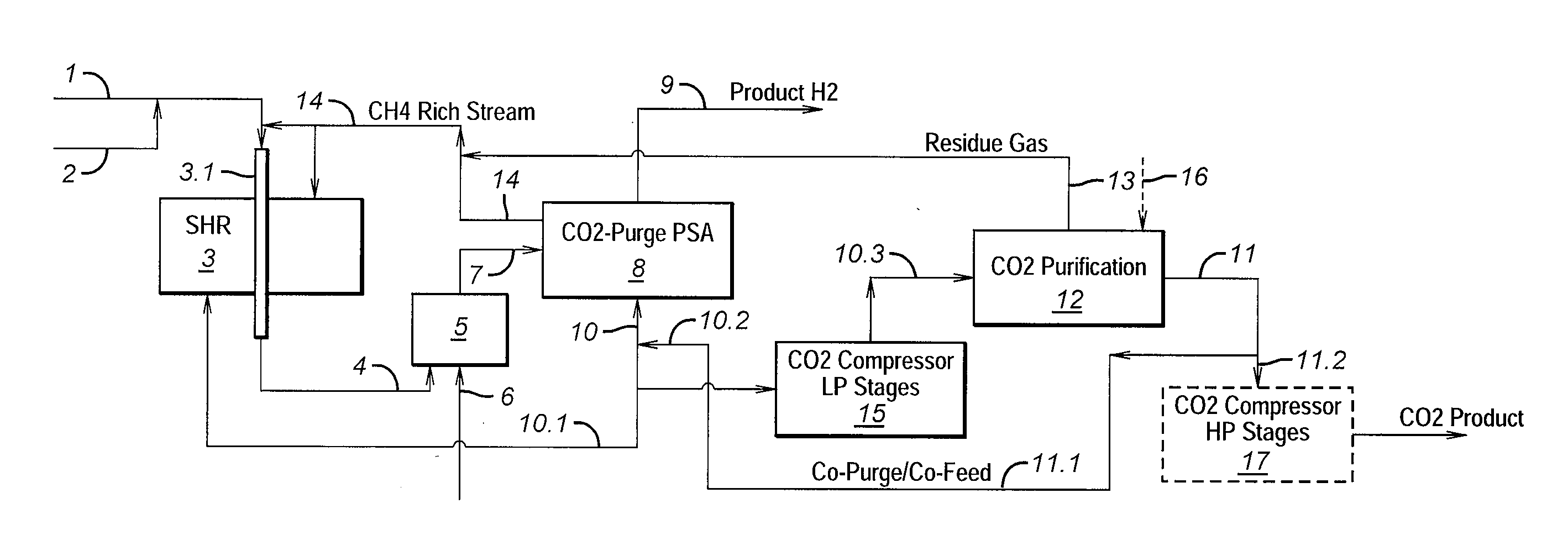
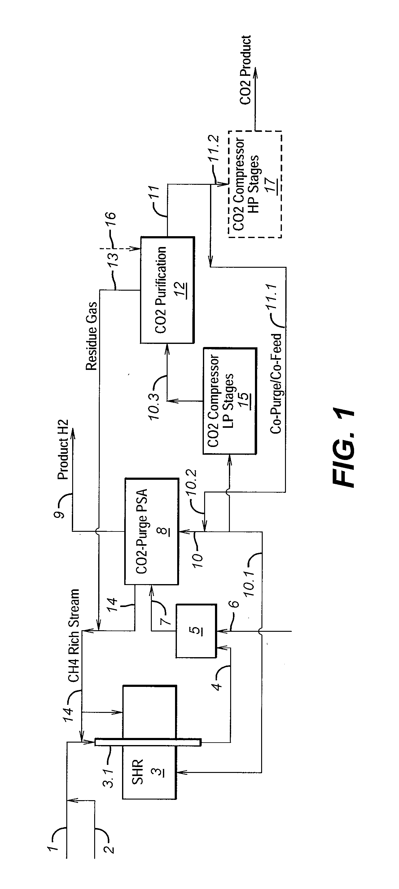
[0017]In the first embodiment as shown in FIG. 1, the SHR unit 3 is used. The present invention is not meant to be limited by the SHR unit 3 or the process for carrying out the reaction in the SHR unit 3. Accordingly, any SHR unit 3 known in the art may be used in the process of the present invention. By way of general description, such SHR units 3 typically contain tubes 3.1 (only one shown in FIG. 1) packed with a SHR catalyst (typically a nickel catalyst) through which the steam 2 / hydrocarbon stream 1 mixture passes. As used throughout with regard to the present invention, the phrase “steam hydrocarbon reformer unit” or “SHR unit” refers not only to the actual reformer units, but also to all of the additional components (not shown) that typically are considered to make up a steam hydrocarbon reformer, including, but not limited to, one or more components selected from heat exchangers, pre-reformer units, the reformer, tubes with one or more types of catalyst, etc. The reaction pr...
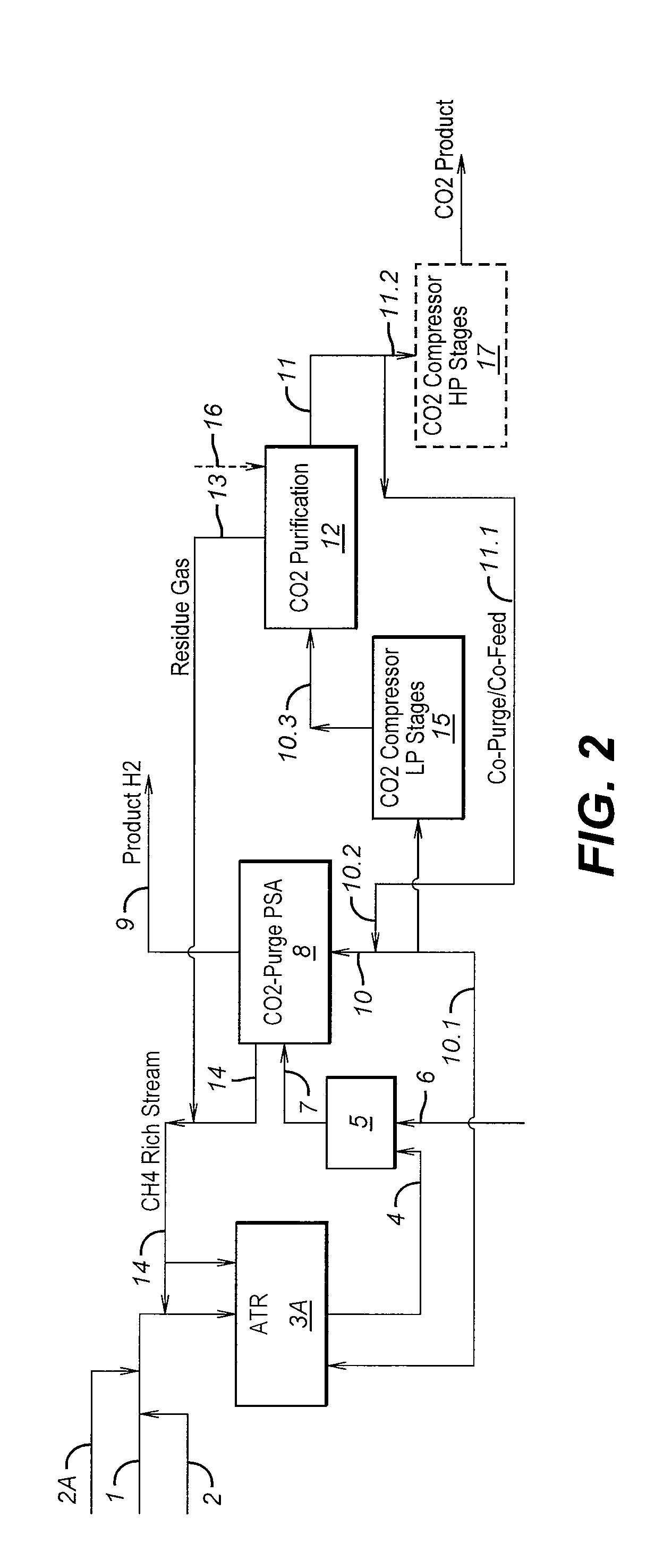
second embodiment

[0035]As noted, the purified CO2 stream is obtained from a CO2 purification unit 12 via line 11. In one embodiment of the present invention, the CO2 purification unit 12 is a CPU unit (specifics not shown). In an alternative embodiment, the CO2 purification unit is a CatOx unit (specifics not shown). Due to the degree of affinity of the various components in the WGS effluent for the adsorbents in the adsorbent beds 19 of the H2 PSA unit 8, the CO2 that is injected from the purified CO2 stream (the co-purge) begins to displace the CH4 and CO that is adsorbed on the adsorbents in the adsorbent beds 19 during the adsorption step of the H2 PSA cycle. The result of this is the displacement of these other components (CH4 and CO) by CO2 on the adsorbents. Consequently, there is a larger concentration of CO2 that is adsorbed on the adsorbents. CH4 and CO displaced from the adsorbent and void spaces in the adsorbent is removed as a gas stream that is CH4 rich but also contains amounts of CO ...


PUM


Abstract

The present invention provides a process for recovering gaseous hydrogen and gaseous carbon dioxide from a mixture of hydrocarbons by utilizing a system that includes a reformer unit, an optional water gas shift reactor, and a pressure swing adsorption unit in conjunction with a carbon dioxide purification unit such as a cryogenic purification unit or a catalytic oxidizer. In this process, purified CO2 from the CO2 purification unit is used as a co-feed / co-purge in the pressure swing adsorption unit in order to produce a CO2 tail gas that includes a higher concentration of CO2.

Description

CROSS-REFERENCE TO RELATED APPLICATIONS[0001]This application claims the benefit of U.S. Provisional Application No. 61 / 225,668, filed Jul. 15, 2009, the entire contents of which are incorporated herein by reference.FIELD OF THE INVENTION[0002]The present invention relates to a process for recovering gaseous hydrogen and gaseous carbon dioxide from a mixture of hydrocarbons by utilizing a system in which a purified carbon dioxide stream produced in a carbon dioxide purification unit is recycled for use as a co-feed to purge the adsorbent beds of a pressure swing adsorption unit used to treat effluent from a reformer unit / water gas shift reactor.BACKGROUND[0003]Interest in the recovery of carbon dioxide (hereinafter “CO2”) from various CO2 containing gas mixtures has increased due to a variety of factors including the merchant CO2 market, enhanced oil recovery and greenhouse gas emissions reduction. The currently available systems for recovering high purity CO2 use a variety of gener...

Claims


Application Information

Patent Timeline
Patent Type & Authority Applications(United States)
IPC IPC(8): F25J3/00
CPCB01D53/047Y02C10/12B01D2256/16B01D2256/24B01D2257/504B01D2259/40054B01D2259/40064B01D2259/402B01D2259/404B01D2259/4148C01B3/36C01B3/382C01B3/384C01B3/48C01B3/56C01B2203/0233C01B2203/0244C01B2203/025C01B2203/0283C01B2203/043C01B2203/047C01B2203/0475C01B2203/048C01B2203/1235C01B2203/148C01B2203/86F25J3/0625F25J3/0655F25J3/067F25J2205/40F25J2205/60F25J2230/30F25J2230/80F25J2245/02F25J2260/80Y02C10/08B01D53/75Y02C20/40Y02P30/00Y02P20/151
Inventor GROVER, BHADRA S.
Owner LAIR LIQUIDE SA POUR LETUDE & LEXPLOITATION DES PROCEDES GEORGES CLAUDE
Why Eureka
Try Eureka