
Method of making a glass preform

a glass preform and glass technology, applied in glass making apparatus, glass deposition burners, manufacturing tools, etc., can solve the problem of low yield of glass preforms, and achieve the effect of high yield

Inactive Publication Date: 2011-01-20
SUMITOMO ELECTRIC IND LTD
View PDF14 Cites 1 Cited by
  • Summary
  • Abstract
  • Description
  • Claims
  • Application Information

AI Technical Summary

Benefits of technology

[0007]The object of the present invention is to provide a method that enables high yield production of glass preforms.
[0010]The glass preform manufacturing method according to the present invention enables high yield production of glass preforms.

Problems solved by technology

In such case, the glass soot body occasionally breaks, resulting in low yield production of glass preforms.

Method used


Image

  • Method of making a glass preform
  • Method of making a glass preform
  • Method of making a glass preform

Examples


examples 1 to 6

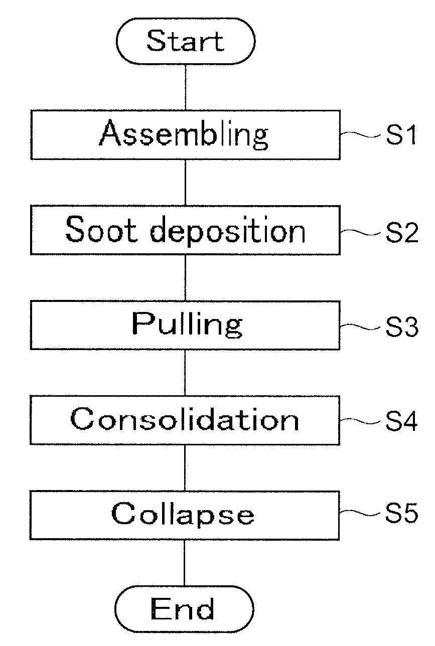
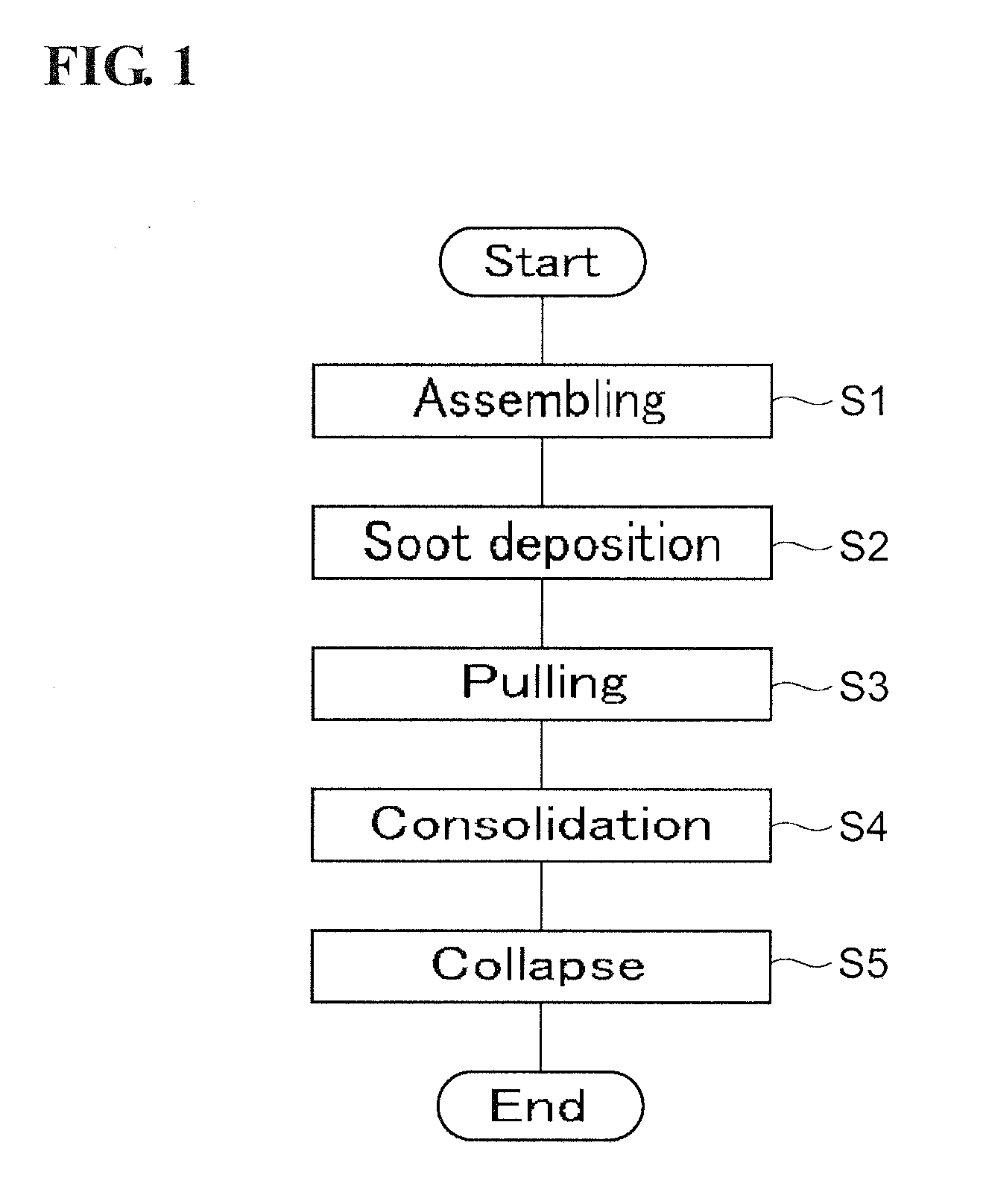
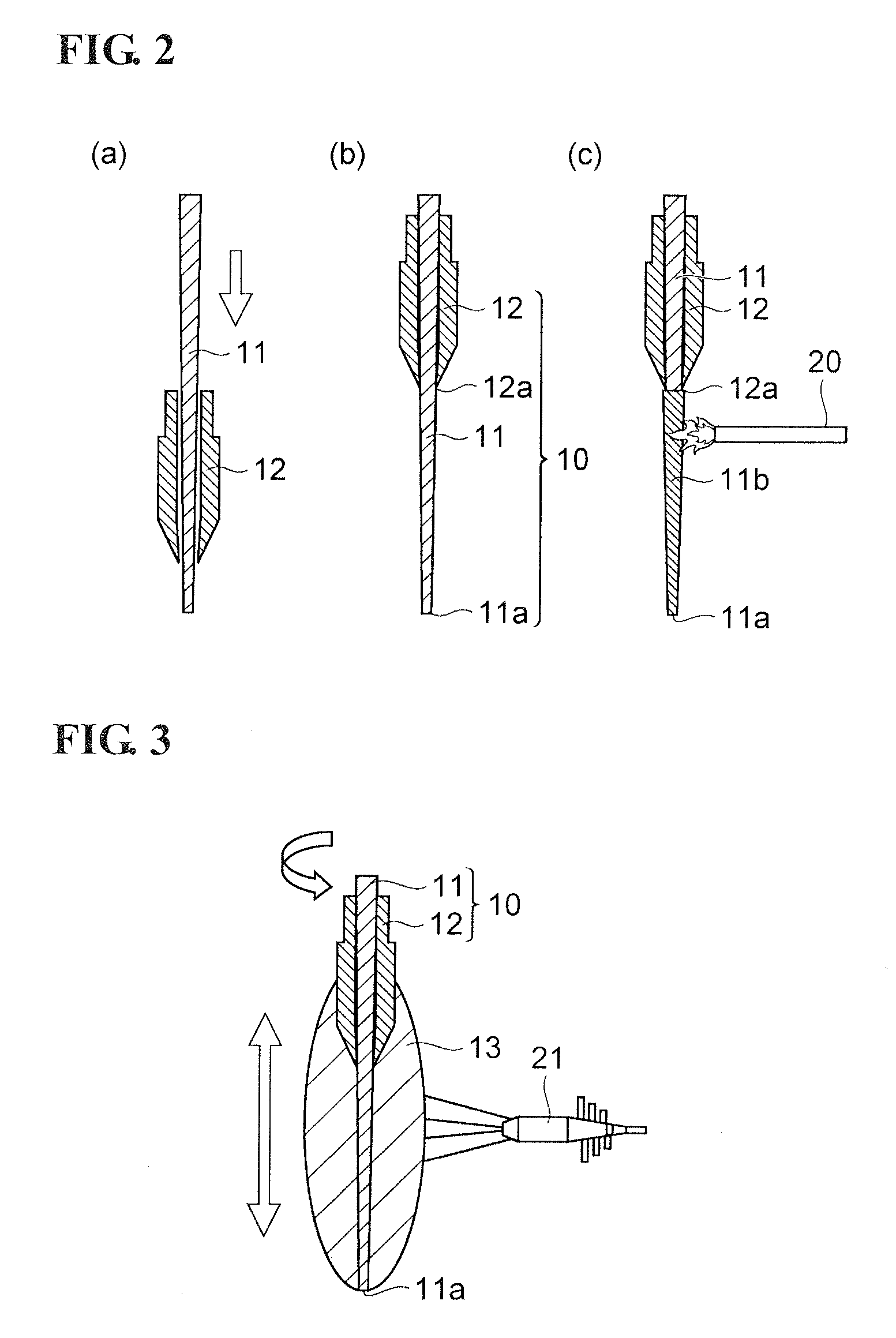
[0032]In Examples 1 to 6, glass preforms which are to be processed into cores of graded-index optical fibers are prepared. Soot deposition step S2 is performed using OVD equipment, a starting mandrel 11 made of alumina having a length of 1200 mm and an outer diameter of 9 to 10 mm, a tubular handle 12 made of silica glass having a length of 600 mm, an outer diameter of 20 to 40 mm, and an inner diameter of 9.8 to 21 mm. The material gas to be supplied to each of the glass synthesizing burner 21 is SiCl4 (charged quantity 1 to 3 SLM) and GeCl4 (charged quantity 0.0 to 0.3 SLM).

[0033]There is a height level difference of about 0.5 mm generated at the end 12a (position P2) of the tubular handle 12. The range in a length of 80 mm to 145 mm including the position P2 is defined as the second range, and the transfer velocity in the second range (P1 to P3) is made lower than the transfer velocity in the first range (P0 to P1). The transfer velocity in the first range (P0 to P1) is 500 mm to...


PUM

PropertyMeasurementUnit
distanceaaaaaaaaaa
inner diameteraaaaaaaaaa

Abstract

The method that enables high yield production of a glass preform comprises an assembling step, a soot deposition step, a pulling step, a consolidation step, and a collapse step. In at least one traverse of the reciprocating movement during the soot deposition step, the relative transfer velocity of the base rod unit and the glass synthesizing burner in a second range is made slower than the relative transfer velocity of the base rod unit and the glass synthesizing burner in a first range, where the first range is a range extending from a boundary position to the tip portion of the starting mandrel and the second range is a range extending from the boundary position to a part of the tubular handle, the boundary position being a position that is 30 mm or more distanced from one end of the tubular handle to the direction of the tip portion of the starting mandrel.

Description

BACKGROUND OF THE INVENTION[0001]1. Field of the Invention[0002]The present invention relates to a method of making a glass preform for optical fiber.[0003]2. Description of the Background Art[0004]An optical fiber is formed by drawing one end of a substantially cylindrical glass preform while it is heated to soften. Also, the glass preform for the optical fiber is produced by a manufacturing method such as the OVD method, the MCVD method, or the like. PCT Application Japanese Translation Publication No. 2002-543026 (Patent document 1) discloses a method for manufacturing a glass preform by the OVD method.[0005]The glass preform manufacturing method of Patent Document 1 intends to manufacture a glass preform for optical fiber with low water content. According to this manufacturing method, a glass soot body is formed by depositing fine glass particles around a starting mandrel and a tubular handle into which the starting mandrel is inserted (deposition process), and then the starting...

Claims


Application Information

Patent Timeline
Patent Type & Authority Applications(United States)
IPC IPC(8): C03B37/02
CPCC03B37/0142C03B2207/66C03B37/01486C03B37/01466
Inventor ISHIHARA, TOMOHIRO
Owner SUMITOMO ELECTRIC IND LTD
Learn More