
Eye detection unit using sequential data flow

a data flow and eye detection technology, applied in the field of eye detection systems and methods, can solve the problems of increasing power consumption, large, expensive, complicated solution, and inefficient use of computing power and power, and achieve the effects of reducing power consumption, reducing latency, and increasing frame ra

Active Publication Date: 2011-01-20
TOBII TECH AB
View PDF9 Cites 58 Cited by
  • Summary
  • Abstract
  • Description
  • Claims
  • Application Information

AI Technical Summary

Benefits of technology

[0009]An object of the present invention is to provide eye detection systems and methods that offer reduced latency, reduced power consumption and increased frame rate in comparison to existing systems.
[0010]A further object of the present invention is to provide eye detection systems and methods for implementation in a computer such as a laptop that offer reduced latency, reduced power consumption and increased frame rate in comparison to existing systems.
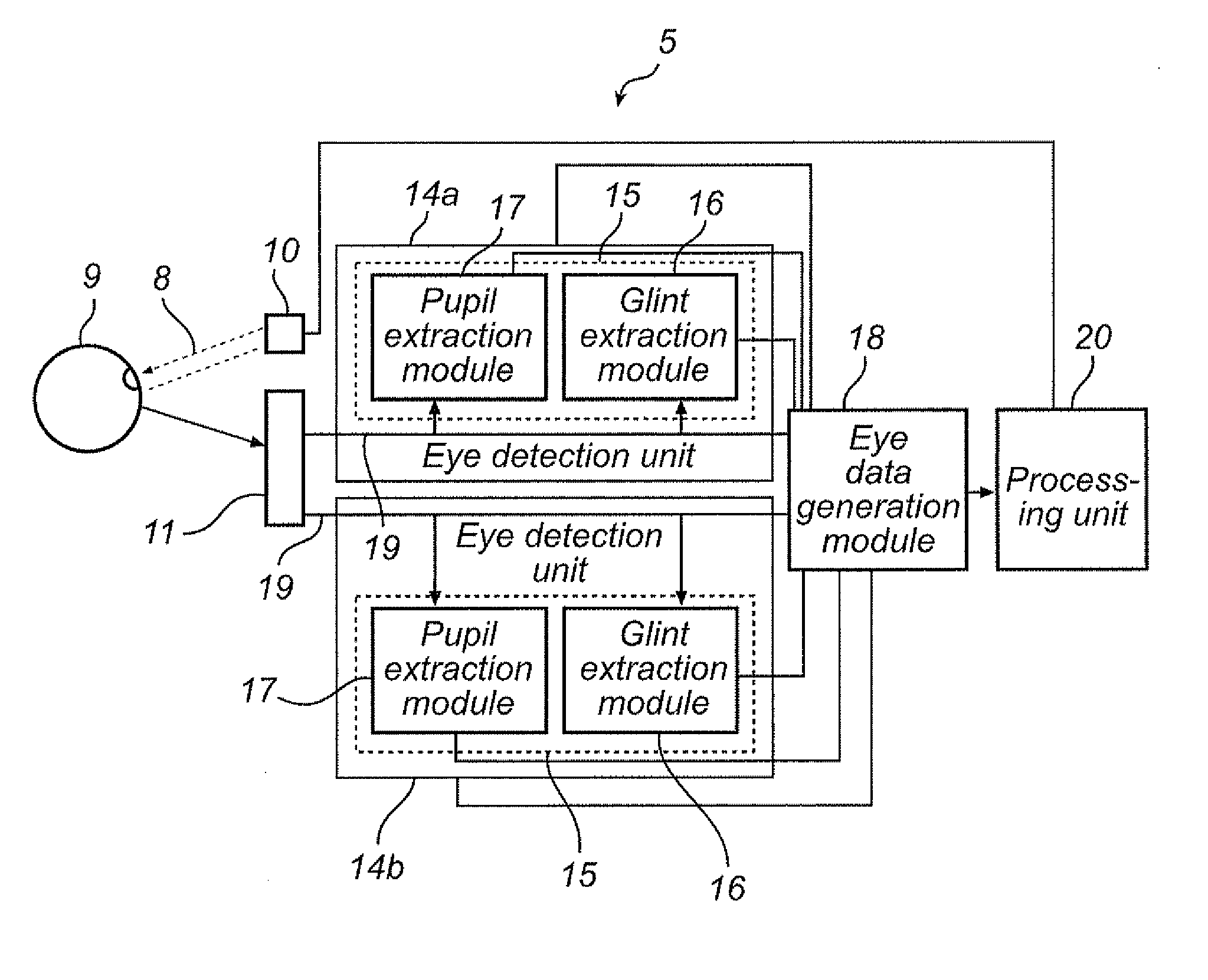
[0022]This inventive concept provides several advantages. For example, due to the eye detection units operating in parallel, where each processes only a subset of the picture elements, and due to that eye data is generated and forwarded to processing only if a potential eye or a potential glint have been identified, reduced latency, reduced power consumption and increased frame rate can be achieved in comparison to existing systems. Further, the system and method of the present invention can be implemented in, for example, a GPU of a computer such as a PC or a laptop offering reduced latency, reduced power consumption and increased frame rate in comparison to existing systems. The present invention can also be used with standard components of the computer including e.g. a web camera. In particular, the system of the present invention can be realized as an embedded eye detection system that can be integrated in a computer such as a laptop. The eye detection system or parts or components of the eye detection system according to the present invention, for example, the eye detection units and the eye data generating module can be implemented in a programmable chip, for example, in a field-programmable gate array (FPGA), in a microprocessor, or in an application-specific integrated circuit (ASIC) or on a graphical processing unit (GPU).

Problems solved by technology

Current commercial and research systems use software implementation and require a dedicated computer for the image-processing—a large, expensive, and complicated-to-use solution.
Further, the eye detection systems of the current dedicated computers are inefficient in terms of use of computing power and power use.
Hence, this system and method processes one image at a time and handles about 30 frames per second and may have difficulties to handle higher frame rates, or may require increased processing power to handle high frame rates, which also may result in an increased power consumption.
Hence, this system suffers from a major bottleneck associated with the data processing rate.
Another problem that may be encountered in the system and method according to U.S. Pat. No. 5,859,686 is that latencies between user action and the experienced response can occur due to the frame by frame handling of the image data, which is annoying for the user.
Thus, this system and method do not satisfies the requirements regarding latency, computing efficiency, power consumption and frame rate of the today's user's.
This system processes one pair of images at a time, which introduces latencies and consumes extra power.

Method used


Image

  • Eye detection unit using sequential data flow
  • Eye detection unit using sequential data flow
  • Eye detection unit using sequential data flow

Examples


Embodiment Construction

[0035]The present invention relates to eye detection systems and methods. The embodiments disclosed herein are merely exemplary or representative of the present invention. The present invention is not to be limited to the specific disclosures presented herein.

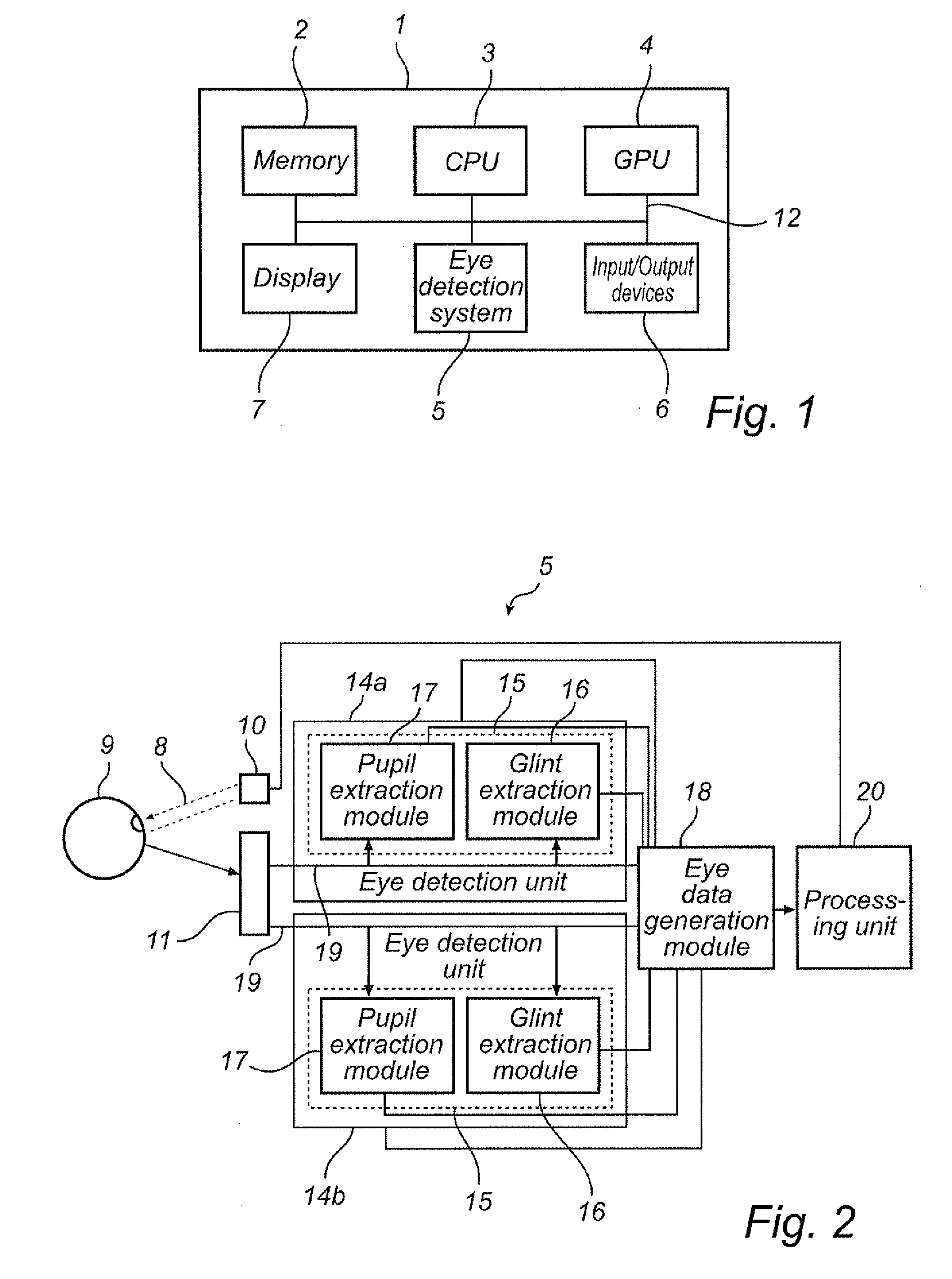
[0036]With reference first to FIGS. 1 and 2, an eye detection system according to the present invention implemented in a computer will be discussed. The system is, for example, capable of determining the point on a monitor or screen at which the computer user is looking / gazing. The determination of the point on a monitor or screen at which the computer user is looking / gazing is performed by tracking the eyes of the user and in particular by determining the gaze angles of the eyes and the position of the eye relatively the monitor. However, the algorithms for the tracking of the eyes and for the determining the gaze angles is not part of the present invention and will not be described in detail herein. The, eye detection system ...


PUM


Abstract

The invention generally relates to systems and methods for eye detection for use in, for example, installations and systems for tracking eyes and gaze angle / directions. The system includes a plurality of eye detection units connected to an image sensor. The eye detection units are adapted to receive regions of picture elements of a digital image frame substantially in parallel and wherein the eye detection units are adapted to operate substantially in parallel, each eye detection unit being adapted to receive a specified region of the picture elements of at least one digital image frame and including an eye feature extraction module adapted to perform a eye feature extraction process on the received picture elements to identify predetermined eye features. An eye data generating module is adapted to receive information of potential identified eye features including picture element coordinates for the identified eye features, and the received region of picture elements, and generate eye data based on the information of potential eye features, wherein the eye data is generated if identified eye features fulfil predetermined conditions, and transfer generated eye data and the received regions of picture elements to a processing module, and wherein a data flow of the eye data and the region of picture elements of a digital image frame is substantially parallel.

Description

FIELD OF THE INVENTION[0001]The invention generally relates to systems and methods for eye detection for use in, for example, installations and systems for tracking eyes and gaze angle / directions. Such a system can for example be used for observing or determining the position on a monitor or display at which a computer user is looking. There are a number of other conceivable applications and such other applications in which the present invention can be used include, inter alia, systems for analysing response on advertisement or systems for predicting driver vigilance and predicting drowsiness and sleep onset of, for example, vehicle drivers. The present invention can be realized as an embedded eye detection system that can be integrated in a computer such as a personal computer (PC) or a laptop. In particular, the present invention relates to eye detection systems and methods that offer reduced latency, reduced power consumption and increased frame rate in comparison to existing sys...

Claims


Application Information

Patent Timeline
Patent Type & Authority Applications(United States)
IPC IPC(8): H04N7/18
CPCA61B3/113G06K9/00604G06F3/013G06V40/19
Inventor HOLMBERG, JOHNNYBLIXT, PETERELVESJO, JOHN
Owner TOBII TECH AB
Learn More