Blur correction apparatus and image capturing apparatus

a technology of blur correction and image capturing, which is applied in the field of blur correction apparatus and image capturing apparatus, can solve problems such as quality degradation of captured images, and achieve the effect of suppressing the degradation of blur correction

Active Publication Date: 2011-01-20
CANON KK
View PDF12 Cites 53 Cited by
  • Summary
  • Abstract
  • Description
  • Claims
  • Application Information

AI Technical Summary

Benefits of technology

[0017]The present invention has been made in consideration of the above-described problem of the prior art, and has as its object to provide a blur correction apparatus capable of suppressing degradation of the blur correction effect even in a panning state.

Problems solved by technology

Quality degradation of a captured image is mainly caused by motion of the image capturing apparatus called device shake or camera shake during exposure, which is especially problematic due to recent size reductions in image capturing apparatuses or increases in the magnification of a zoom lens.

Method used


Image

  • Blur correction apparatus and image capturing apparatus
  • Blur correction apparatus and image capturing apparatus
  • Blur correction apparatus and image capturing apparatus

Examples


first embodiment

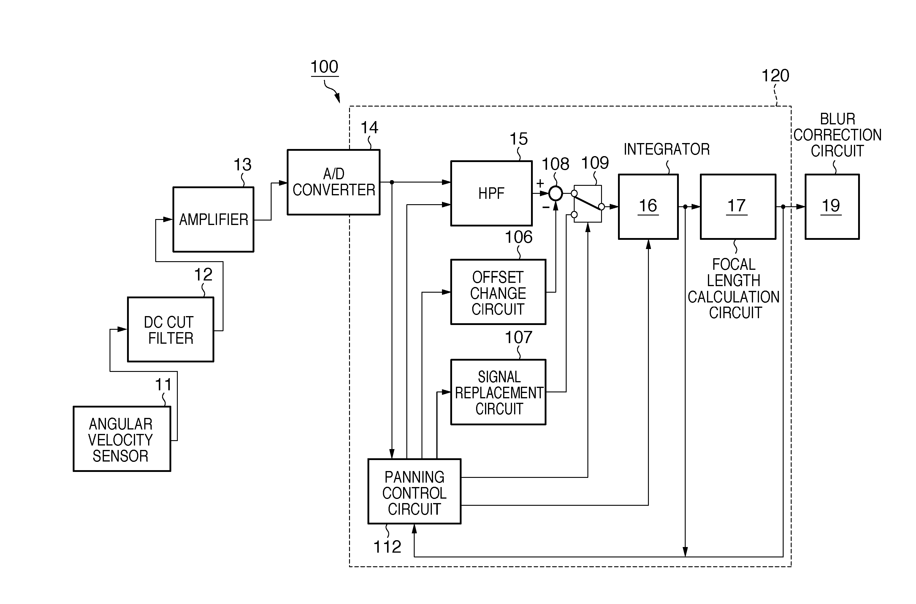
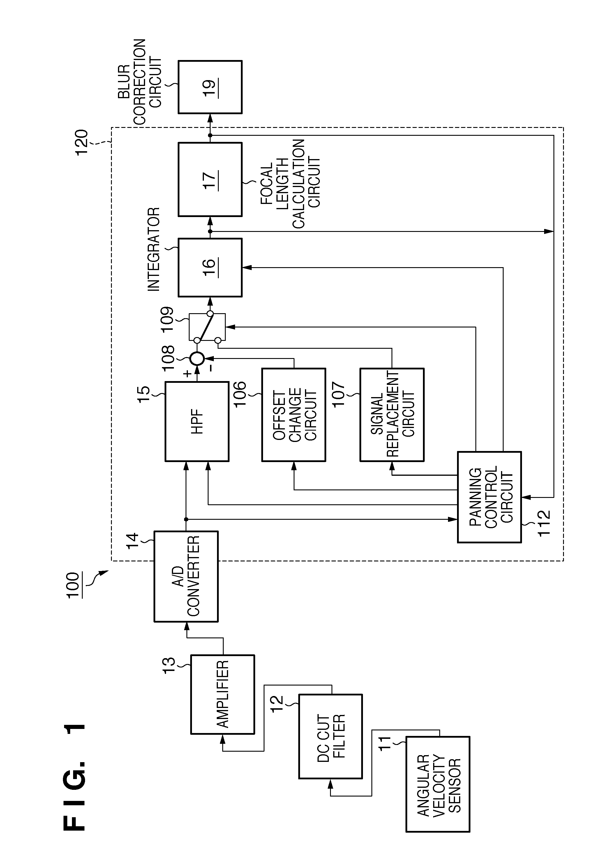
[0065]The operation of a panning control circuit 112 according to the first embodiment of the present invention will be described below. Note that in this embodiment, a signal replacement circuit 107 and a switch 109 are not indispensable, and the output from an adder-subtracter 108 may directly be input to an integrator 16.

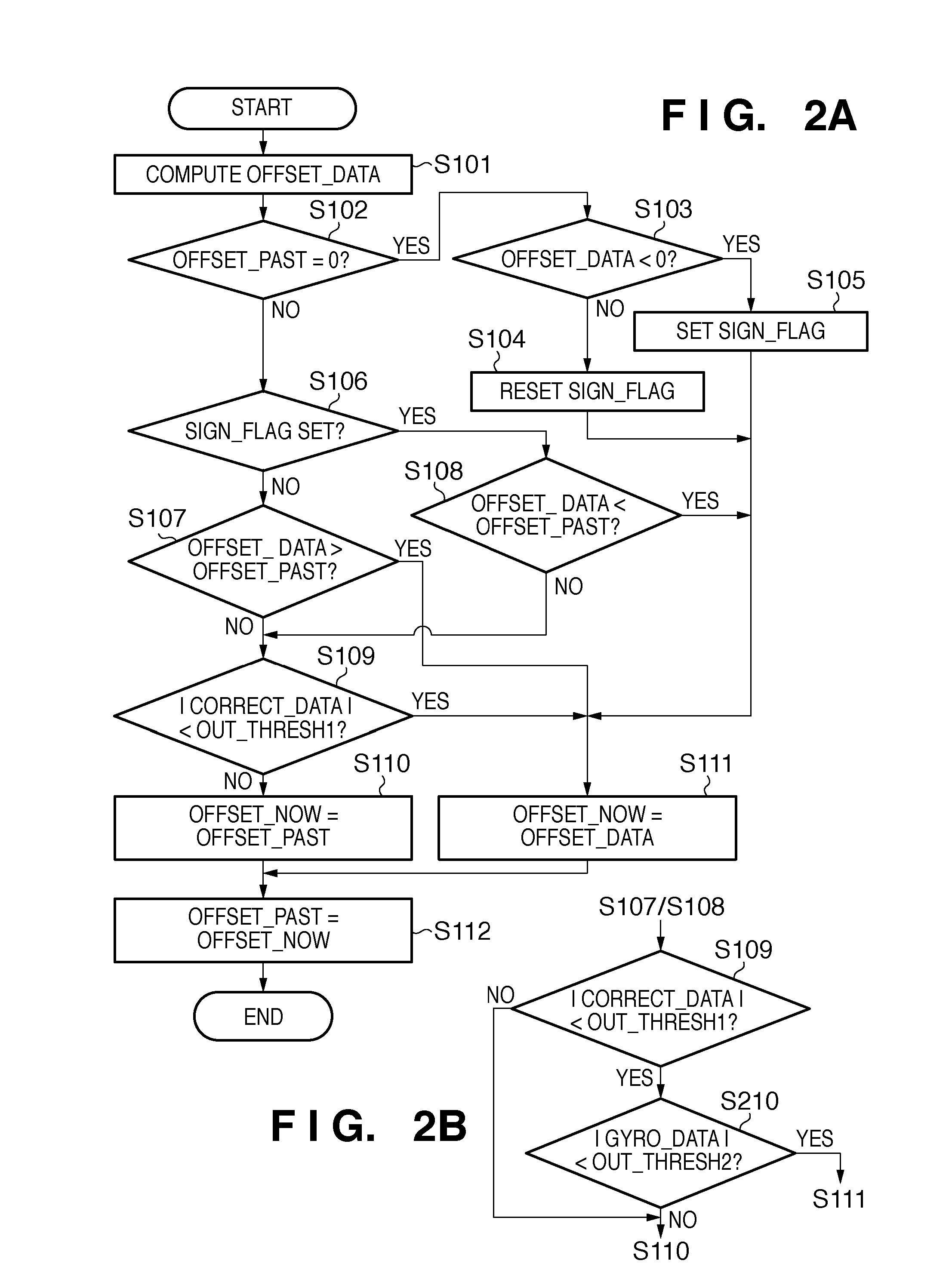
[0066]FIG. 2A is a flowchart for explaining panning control processing performed by the panning control circuit 112 according to the first embodiment. Note that the processing to be described below with reference to FIG. 2A is repeatedly performed at a predetermined interval, for example, for every vertical sync period ( 1 / 60 sec).

[0067]In step S101, the panning control circuit 112 computes the value of a variable OFFSET_DATA to be used to decide the output signal of an offset change circuit 106. Note that the output signal of the offset change circuit 106 in the current panning control processing will be defined as OFFSET_NOW, and the output signal of the offset...

second embodiment

[0091]The second embodiment of the present invention will be described next. This embodiment is characterized in that a panning start determination threshold IN_THRESH1 and a panning end determination threshold OUT_THRESH1, which are fixed in the first embodiment, are changed in accordance with the focal length (angle of view) of a zoom lens with a variable focal length in an image capturing apparatus.

[0092]FIG. 6A is a graph showing the relationship between the panning start determination threshold IN_THRESH1 and the focal length of the zoom lens according to this embodiment. As shown in FIG. 6A, a panning control circuit 112 of this embodiment sets the panning start determination threshold IN_THRESH1 to be smaller as the focal length of the zoom lens increases (the angle of view decreases).

[0093]Letting θ be angular displacement data output from an integrator 16, and f be the focal length data of the zoom lens, shake correction data CORRECT_DATA output from a focal length calculat...

third embodiment

[0097]The third embodiment of the present invention will be described next. This embodiment is characterized in that the absolute value of correction data is smaller than a panning end determination threshold OUT_THRESH1, and a panning state is determined to have ended when the absolute value of angular velocity data (GYRO_DATA) satisfies a condition. Note that in this embodiment, a signal replacement circuit 107 and a switch 109 are not indispensable, and the output from an adder-subtracter 108 may directly be input to an integrator 16.

[0098]FIG. 2B is a flowchart for explaining, out of panning control processing performed by a panning control circuit 112 according to the third embodiment, operations different from the first embodiment. The panning control processing of the third embodiment is the same as that of the first embodiment except that angular velocity data determination processing (S210) is added between steps S109 and S111. Only the different processing will be describe...


PUM


Abstract

Upon detecting the start of a panning operation, an adder-subtracter applies an offset from an offset change circuit to the output of an HPF (High-Pass Filter) representing the shake amount of an image capturing apparatus to decrease the shake amount. The offset value is set to be larger as the value of shake correction data output from a focal length calculation circuit is closer to the correction limit of a blur correction circuit. Upon detecting the end of the panning operation, the offset value is returned to zero. This invention provides a blur correction apparatus capable of suppressing degradation of a blur correction effect even when in a panning state.

Description

BACKGROUND OF THE INVENTION[0001]1. Field of the Invention[0002]The present invention relates to a blur correction apparatus that corrects blur in a captured image caused by motion (shake) of an image capturing apparatus. The present invention also relates to an image capturing apparatus comprising the blur correction apparatus.[0003]2. Description of the Related Art[0004]Quality degradation of a captured image is mainly caused by motion of the image capturing apparatus called device shake or camera shake during exposure, which is especially problematic due to recent size reductions in image capturing apparatuses or increases in the magnification of a zoom lens. Accordingly, a blur correction apparatus for reducing the influence (blur) of device shake on a captured image has been proposed.[0005]On the other hand, there exists an image capturing method such as follow shot that captures an image while intentionally moving the image capturing apparatus. It is not preferable to apply bl...

Claims


Application Information

Patent Timeline
Patent Type & Authority Applications(United States)
IPC IPC(8): H04N5/217H04N5/228
CPCG02B27/646H04N5/23248H04N5/23287H04N5/23261H04N5/23258H04N23/68H04N23/6815H04N23/687H04N23/6812
Inventor MIYASAKO, KENICHI
Owner CANON KK
Why Eureka
Try Eureka