
Liquid crystal display device with an anisotropically reflecting layer and manufacturing method for the same

a liquid crystal display and anisotropic reflection technology, applied in the direction of mirrors, instruments, chemistry apparatus and processes, etc., to achieve the effect of improving a quality of displaying and maximizing the utilization of directivity

Active Publication Date: 2011-01-20
INNOLUX CORP
View PDF6 Cites 9 Cited by
  • Summary
  • Abstract
  • Description
  • Claims
  • Application Information

AI Technical Summary

Benefits of technology

[0010]The present invention has been implemented in view of the above-described problem and its object is to provide a liquid crystal display device which maximizes the utilization of the directivity of the diffused reflected light distribution of the diffusive reflecting layer and can further improve a quality of displaying.
[0011]It is another object of the present invention to achieve efficient improvement of contrast characteristics, which is suitable to a liquid crystal display device comprising a diffusive reflecting layer having diffused reflected light distribution with a directivity.
[0013]This gives substantially constant retardation independent of viewing angles to the reflected light in the direction along the specific plane, which behaves like direct reflection, and thereby it is possible to reduce dependence of contrast on the viewing angle in the direction along the specific plane. Therefore, it is possible to provide the brightest possible image display with high visibility even in the direction along the specific plane.
[0015]In this aspect, the specific direction and the other direction may have a substantially perpendicular relations. This allows the liquid crystal display device having diffused reflected light distribution with a directivity in directions perpendicular to each other to be further improved in respect of a quality of displaying. Setting the specific direction in particular to the vertical direction of the display face of the liquid crystal display device and setting the other direction to the horizontal direction of the display face is suitable for the liquid crystal display device used in portable devices. Since a display face of this type of display device is overwhelmingly more often viewed by changing the viewing angle horizontally than it is viewed by changing the viewing angle vertically, the ability to maintain a bright image when the viewing angle is changed horizontally is very effective and at the same time assures stability of contrast also when the viewing angle is changed vertically.
[0016]In the liquid crystal display device, the diffusive reflecting layer may have a reflecting surface showing roughness of shape based on a plurality of island-shaped outline units of depression or projection portions, and an average diameter of the units of depression or projection portions in the specific direction may be greater than an average diameter in a direction substantially perpendicular to the specific direction on the principal plane of the diffusive reflecting layer, and alternatively, an average pitch of the units of depression portions or the units of projection portions in the specific direction may be greater than an average pitch of them in a direction substantially perpendicular to the specific direction on the principal plane of the diffusive reflecting layer. This has advantages that a desired directivity can be added to the diffused reflected light distribution of the diffusive reflecting layer relatively simply and in sophistication.

Problems solved by technology

However, such a liquid crystal display device with a diffused reflected light distribution having a predetermined directivity is not intended to improve a quality of displaying by maximizing the utilization of the directivity in addition to effective use of light, which is achieved by adaptation for the above-described mode of use.

Method used


Image

  • Liquid crystal display device with an anisotropically reflecting layer and  manufacturing method for the same
  • Liquid crystal display device with an anisotropically reflecting layer and  manufacturing method for the same
  • Liquid crystal display device with an anisotropically reflecting layer and  manufacturing method for the same

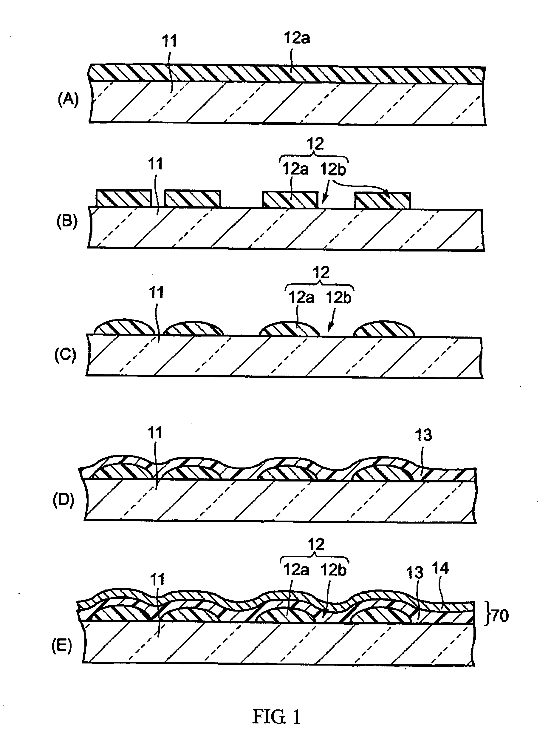
Examples


Embodiment Construction

)

[0028]With reference to the attached drawings, the above aspects and other aspects of the present invention will be described based on embodiments in more detail below.

[0029]First, the diffusive reflecting layer used in embodiments of the present invention will be explained.

[0030]FIG. 1 shows a sectional structure of a member forming the diffusive reflecting layer in the respective steps of a manufacturing method for a diffusive reflecting layer.

[0031]In a first step (A), a support member 11 made of glass, for example, is prepared and a photoresist material of e.g. negative type is applied to the entire surface of this support member 11 to a thickness of 2 μm to form a resist film 12a. Then, after conducting prebaking, the resist film 12a is exposed to light using a photomask.

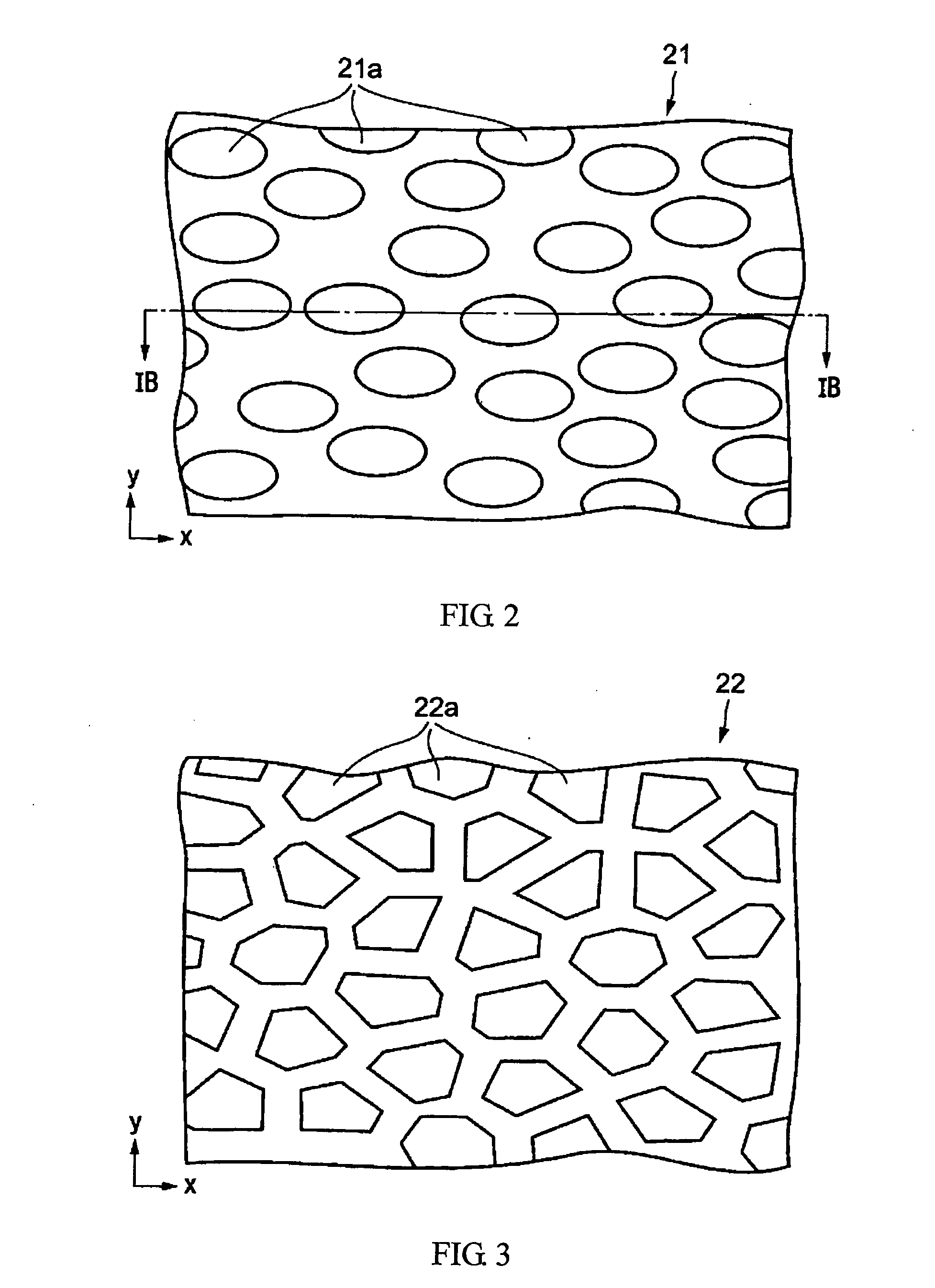
[0032]FIG. 2 is a plan view schematically showing an example of photomask used for such exposure.

[0033]This mask has a plurality of openings 21a arranged away from one another and these openings 21a have an el...


PUM

PropertyMeasurementUnit
thicknessaaaaaaaaaa
diameteraaaaaaaaaa
lengthaaaaaaaaaa

Abstract

A liquid crystal display device comprises an optically diffusively reflecting layer arranged to maximize utilization of incident light. The reflecting layer contains a thin metallic film with projections (14a) each having an unsymmetrical cross section to centralise reflected light in a specific azimuth direction (y). The range of viewing angles (θx-z, θy-z) into which a substantial portion of the incident light is reflected is broader in the specific azimuth direction (y) than in another direction (x). The director (5d) of liquid crystal molecules initiallly lies in a plane (y-z) parallel to the specific azimuth direction (y) to achieve retardation self-compensation.

Description

BACKGROUND OF THE INVENTION[0001]1. Field of the Invention[0002]The present invention relates to a reflective or transflective liquid crystal display device and its manufacturing method. The invention especially relates to a liquid crystal display device having a diffusive reflecting layer providing distribution of diffused reflected light with a specific directivity.[0003]2. Description of the Related Art[0004]Prior to now, there has been a reflective liquid crystal display device provided with a liquid crystal layer for performing optical modulation in accordance with an image to be displayed and a diffusive reflecting layer disposed on the back side opposite to the display face is conventionally available. Such a display device causes light, which has been incident from the front side of the display device and has passed through the liquid crystal layer, to be diffusively reflected by the diffusive reflecting layer and returned to the display face side through the liquid crystal ...

Claims


Application Information

Patent Timeline
Patent Type & Authority Applications(United States)
IPC IPC(8): G02F1/1335G02F1/03G02B5/02G02B5/08G02F1/1337
CPCG02F1/133504G02F2001/133565G02F1/1337G02F1/133553G02F1/133565
Inventor TAKAHASHI, SATORU
Owner INNOLUX CORP
Learn More