Mobile communication system, base station device, mobile station device, and mobile communication method

a mobile communication system and mobile station technology, applied in the field of mobile communication systems, can solve the problems of inability to ensure the operation of the mobile station device in that area, inability to use the reception quality for the handover reference, and inability to recognize the cell id of the mobile station device in the same cell (cid_b), etc., to achieve the effect of simplifying the communication process

Active Publication Date: 2011-01-20
SNAPTRACK
View PDF3 Cites 36 Cited by
  • Summary
  • Abstract
  • Description
  • Claims
  • Application Information

AI Technical Summary

Benefits of technology

[0060]According to the present invention, the base station device notifies the mobile station device of the presence of the conflicting cell, such that the mobile station device can communicate with the base station device based on the presence of the conflicting cell. Accordingly, since exchange of unnecessary radio signals with a base station device of the conflicting cell does not occur, it is possible to simplify the process in the communication between the mobile station device and the base station device.

Problems solved by technology

In fact, the random access is performed by using a (contention-based) channel which may cause conflict.
However, in the cell search procedure and the handover procedure of the conventional art, when the same cell ID is allocated to the base station device, that is, a plurality of base station devices having the same primary synchronization channel (P-SCH) and secondary synchronization channel (S-SCH) are in an area, it is not possible to guarantee the operation of the mobile station device in that area.
However, in the cell search procedure of the conventional art, since the mobile station device can detect only 2 types of cell IDs of CID_A and CID_B, the mobile station device cannot recognize if there are two cells having the same cell ID (CID_B).
In addition, when it is reported that the reception quality of the CID_B cell is acquired by synthesizing the reception qualities of the neighboring cell (CID_B) and the conflicting cell (CID_B), the reception quality cannot be suitably used for the handover reference.
Further, even when the source cell (CID_A) transmits the handover command message to the neighboring cell (CID_B) to the mobile station device, it is not possible to clearly designate the neighboring cell (CID_B) as the cell of the handover destination.
However, it is difficult for the mobile station device to autonomously detect the allocation of the same cell ID, and divide and receive each of the radio signals.
For this reason, when there is a conflicting cell, a problem arises in that the process in the communication between the mobile station device and the base station device becomes complicated.

Method used


Image

  • Mobile communication system, base station device, mobile station device, and mobile communication method
  • Mobile communication system, base station device, mobile station device, and mobile communication method
  • Mobile communication system, base station device, mobile station device, and mobile communication method

Examples


first embodiment

[0122]First, a first embodiment of the present invention will be described.

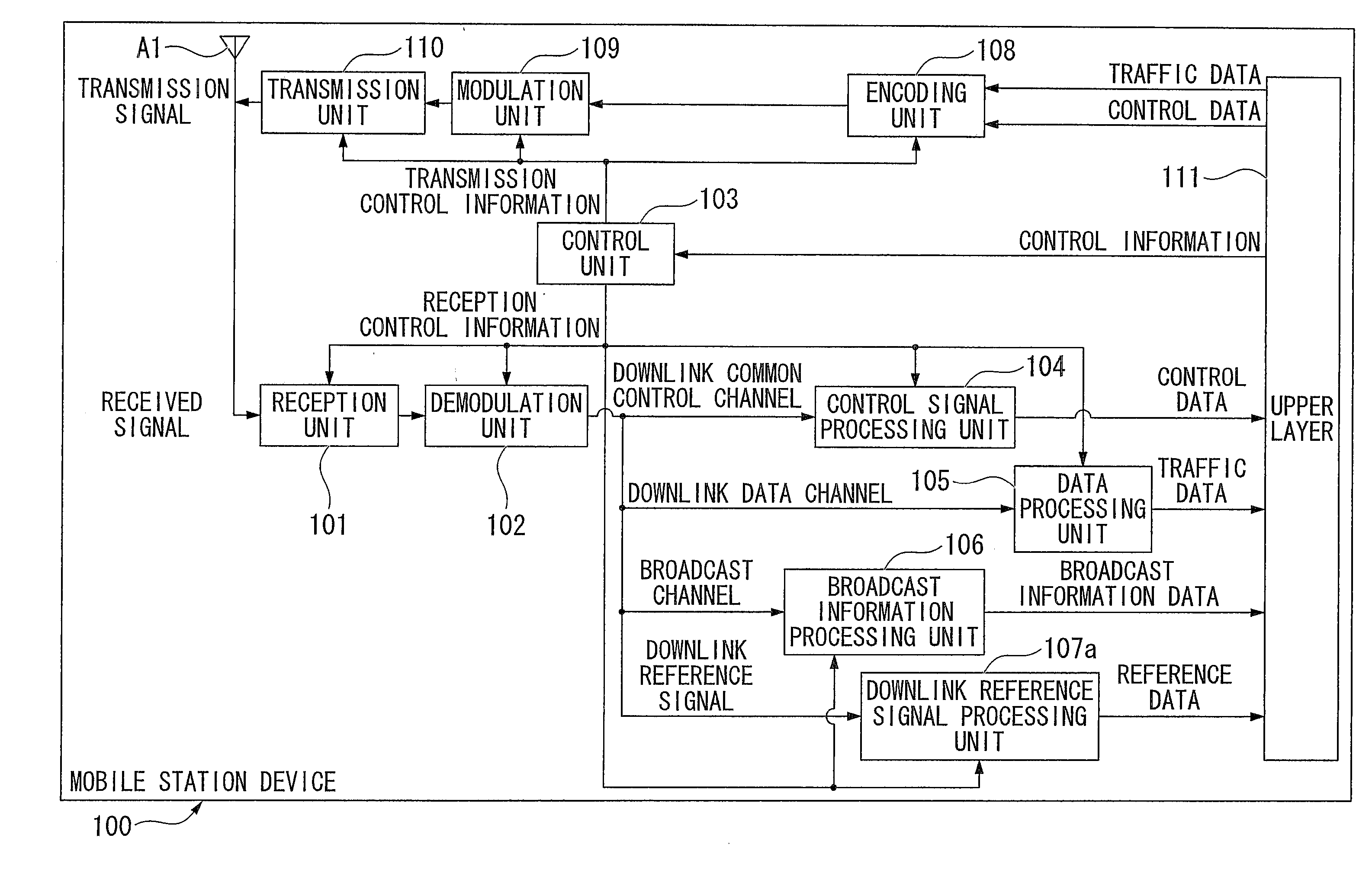
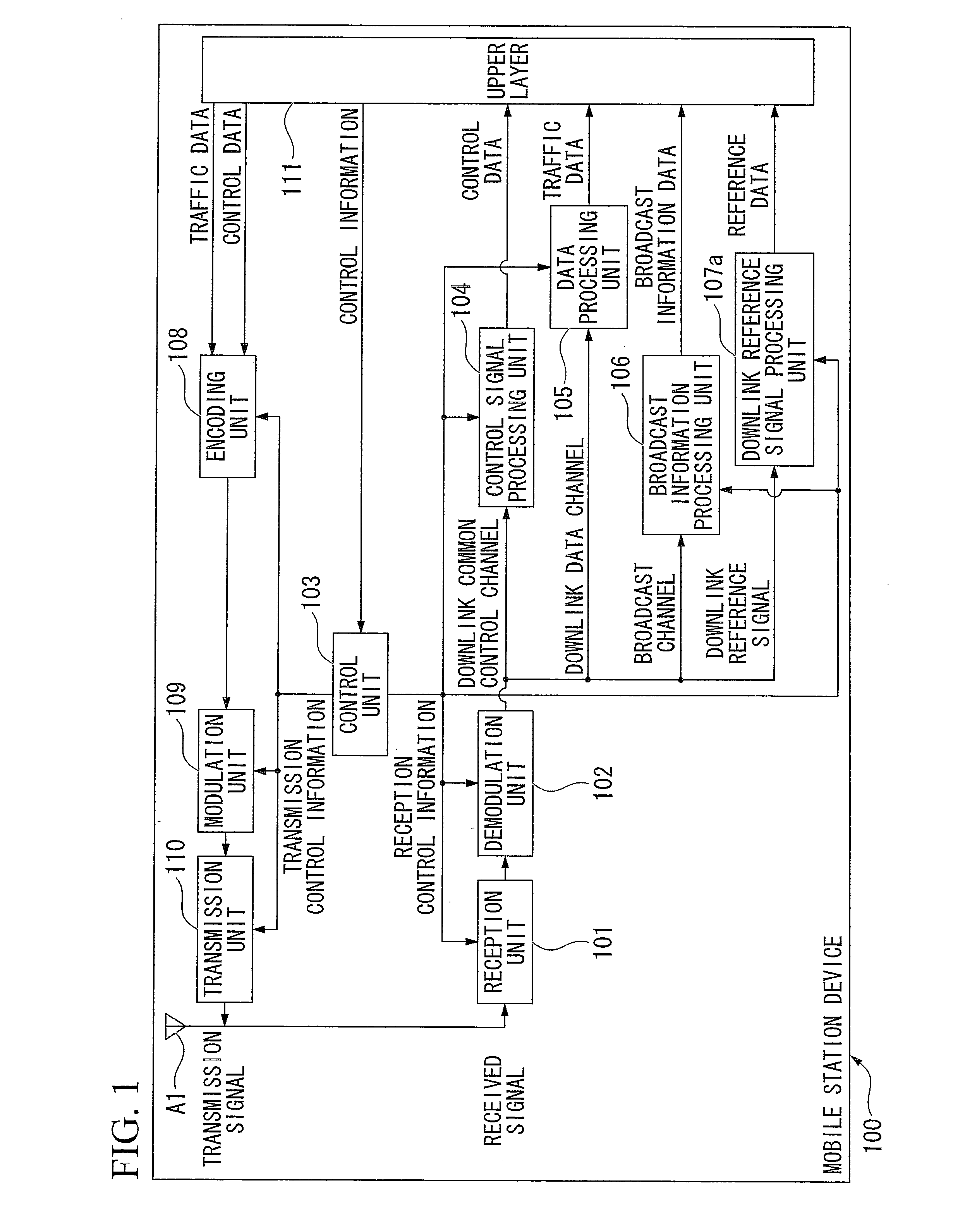
[0123]FIG. 1 is a schematic block diagram showing a configuration of a mobile station device 100 according to the first embodiment of the present invention. The mobile station device 100 includes a reception unit 101, a demodulation unit 102, a control unit 103 (also referred to as a handover processing unit), a control signal processing unit 104, a data processing unit 105, a broadcast information processing unit 106, a downlink reference signal processing unit 107a, an encoding unit 108, a modulation unit 109, a transmission unit 110 (also referred to as a measurement result transmission unit), an upper layer 111, and an antenna A1.

[0124]A received signal (a transmission signal from the base station device) is received by the reception unit 101 via the antenna A1. The received signal is output to the demodulation unit 102 and demodulated based on reception control information input from the control unit 103...

second embodiment

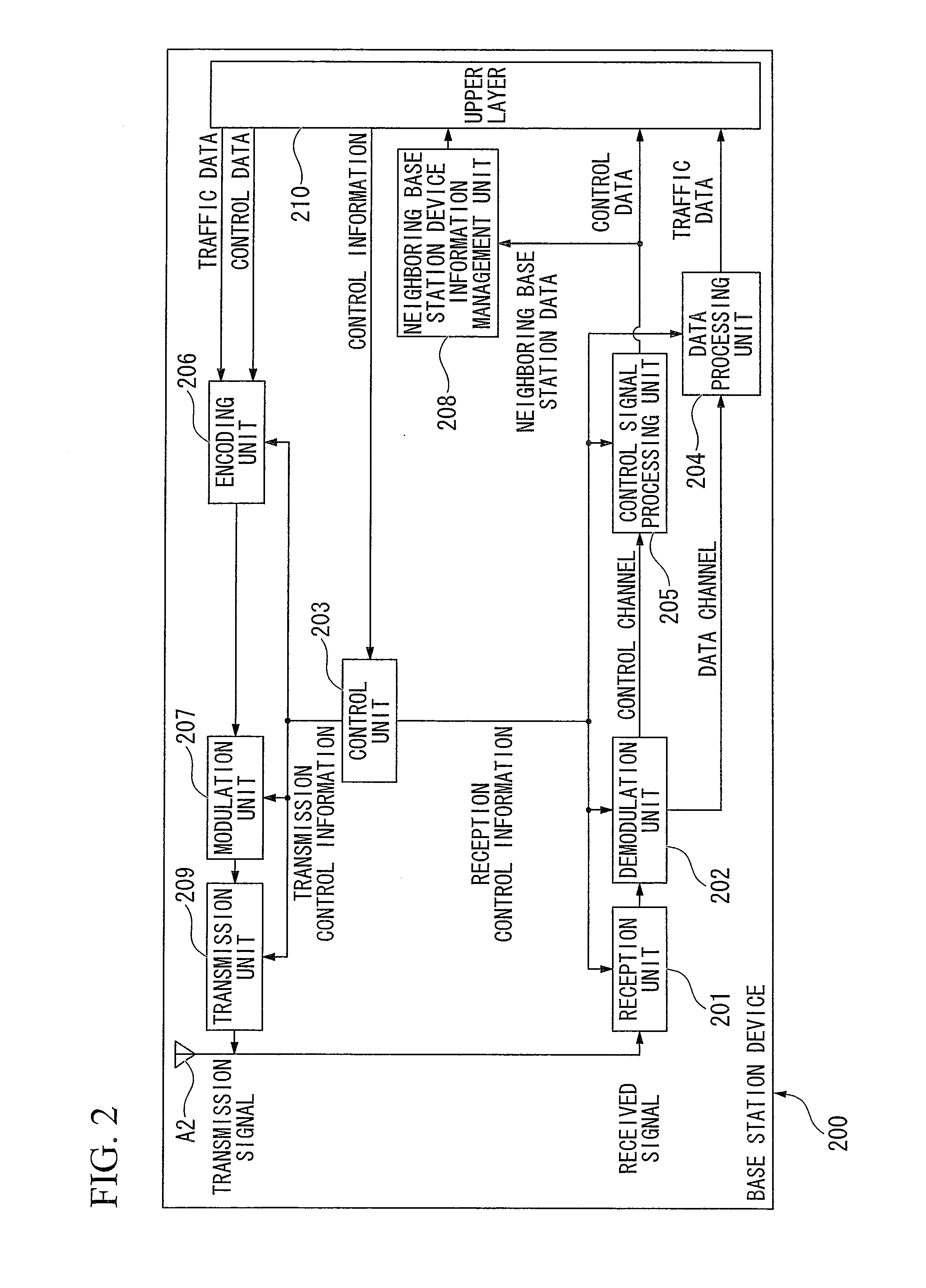
[0173]Next, a second embodiment of the present invention will be described. A mobile communication system according to the second embodiment includes a base station device and a mobile station device. Since the configurations of the base station device and the mobile station device according to the second embodiment are the same as those of the base station device 200 (FIG. 2) and the mobile station device 100 (FIG. 1) according to the first embodiment, a description thereof is omitted.

[0174]However, the mobile station device 100 according to the second embodiment includes a downlink reference signal processing unit 107b instead of the downlink reference signal processing unit 107a.

[0175]The second embodiment provides a structure in which the mobile station device 100 acquiring the conflicting cell ID information can identify the reception quality of each of the conflicting cell IDs by receiving the GCID before the measurement report process.

[0176]The present embodiment is preferab...

third embodiment

[0220]Next, a third embodiment of the present invention will be described. A mobile communication system according to the third embodiment includes a base station device and a mobile station device. Since the configurations of the base station device and the mobile station device according to the third embodiment are the same as those of the base station device 200 (FIG. 2) and the mobile station device 100 (FIG. 1) according to the first embodiment, a description thereof is omitted.

[0221]The third embodiment provides a structure capable of identifying a cell accessed after handover by including conflicting cell ID information in a handover command message.

[0222]FIG. 12 is a sequence diagram showing a handover procedure according to the third embodiment of the present invention. FIG. 12 shows the handover procedure in the event of conflict of the cell ID.

[0223]The relationship of the mobile station device 100, serving cells and neighboring cells is the same as that of FIG. 3. In add...


PUM


Abstract

A mobile communication system includes a mobile station device and a base station device. The base station device includes a cell identification information transmission unit which transmits cell identification information of base station devices transmitting radio signals of the same synchronization channel, to the mobile station device when there are at least two base station devices transmitting radio signals of the same synchronization channel within a predetermined communication area. The mobile station device includes a measurement result transmission unit which performs a measurement process based on the cell identification information of the base station devices and transmits the measurement result acquired by the measurement process to the base station device.

Description

TECHNICAL FIELD[0001]The present invention relates to a mobile communication system, a base station device, a mobile station device, and a mobile communication method.[0002]This application claims priority to and the benefits of Japanese Patent Application No. 2008-024400 filed on Feb. 4, 2008, the disclosure of which is incorporated herein by reference.BACKGROUND ART[0003]Recently, Evolved Universal Terrestrial Radio Access (hereinafter, referred to as “EUTRA”) aimed at high speed communication has been examined by a standardized group, 3rd Generation Partnership Project (3GPP), by introducing technology examined for a 4th generation frequency bandwidth into a 3rd generation frequency bandwidth (Non-Patent Document 1).[0004]In EUTRA, as a communication method, Orthogonal Frequency Division Multiplexing Access (OFDMA) is used. OFDMA is a communication method which is strong against multi-path interference and suitable for high speed transmission. In addition, a specification for an ...

Claims


Application Information

Patent Timeline
Patent Type & Authority Applications(United States)
IPC IPC(8): H04W36/12
CPCH04W24/10H04W36/0061H04W36/36H04W48/10H04W56/0085H04W36/08H04W36/0085H04W36/30
Inventor UEMURA, KATSUNARITSUBOI, HIDEKAZU
Owner SNAPTRACK
Why Eureka
Try Eureka