Active optical cable apparatus and method for detecting optical fiber breakage

Inactive Publication Date: 2011-01-20
AVAGO TECHNOLOGIED FIBER IP SINGAPORE PTE LTD
View PDF29 Cites 51 Cited by
  • Summary
  • Abstract
  • Description
  • Claims
  • Application Information

AI Technical Summary

Benefits of technology

[0011]The active optical cable apparatus and method involve controlling the operation of the active optical cable based on the detection of signal loss, e.g., due to fiber breakage, within the active optical cable. The active optical cable includes first and second optical transceivers, each optical transceiver with an open fiber control module or other appropriate configuration coupled between the transmission side and the receiver side of the respective optical transceiver. The transmission side of each optical transceiver is coupled to the receiver side of the other optical transceiver via a plurality of transmission channels, such as a plurality of optical fibers. Each open fiber control module is configured to detect the optical power level of optical signals received by the receiver side of the optical transce

Problems solved by technology

However, as data transmission rates approach 10 Gbit/sec, the data transfer qualities of copper cabling begins to suffer.
However, when an optical fiber within the optical fiber cable is cut or broken, the laser emission resulting from the malfunction still needs to be at or below an eye-safe level to meet existing safety standards.
However, optical power att

Method used


Image

  • Active optical cable apparatus and method for detecting optical fiber breakage
  • Active optical cable apparatus and method for detecting optical fiber breakage
  • Active optical cable apparatus and method for detecting optical fiber breakage

Examples


Embodiment Construction

[0015]In the following description, like reference numerals indicate like components to enhance the understanding of the active optical cable apparatus and methods through the description of the drawings. Also, although specific features, configurations and arrangements are discussed hereinbelow, it should be understood that such specificity is for illustrative purposes only. A person skilled in the relevant art will recognize that other steps, configurations and arrangements are useful without departing from the spirit and scope of the invention.

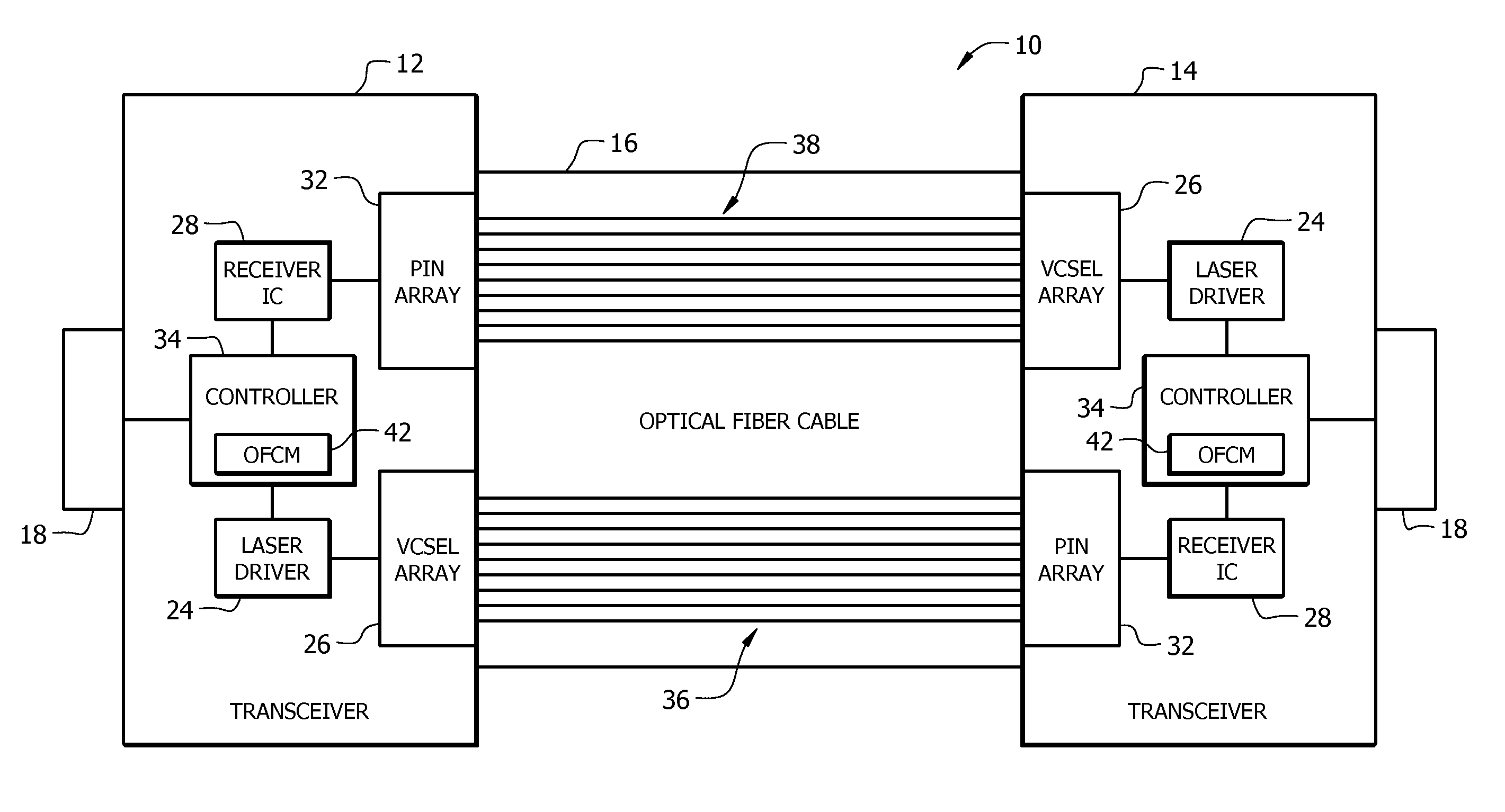
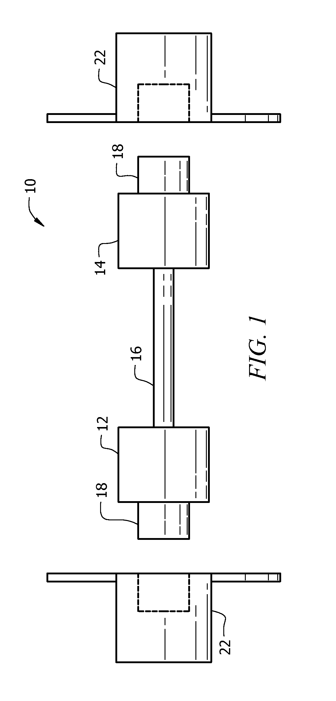
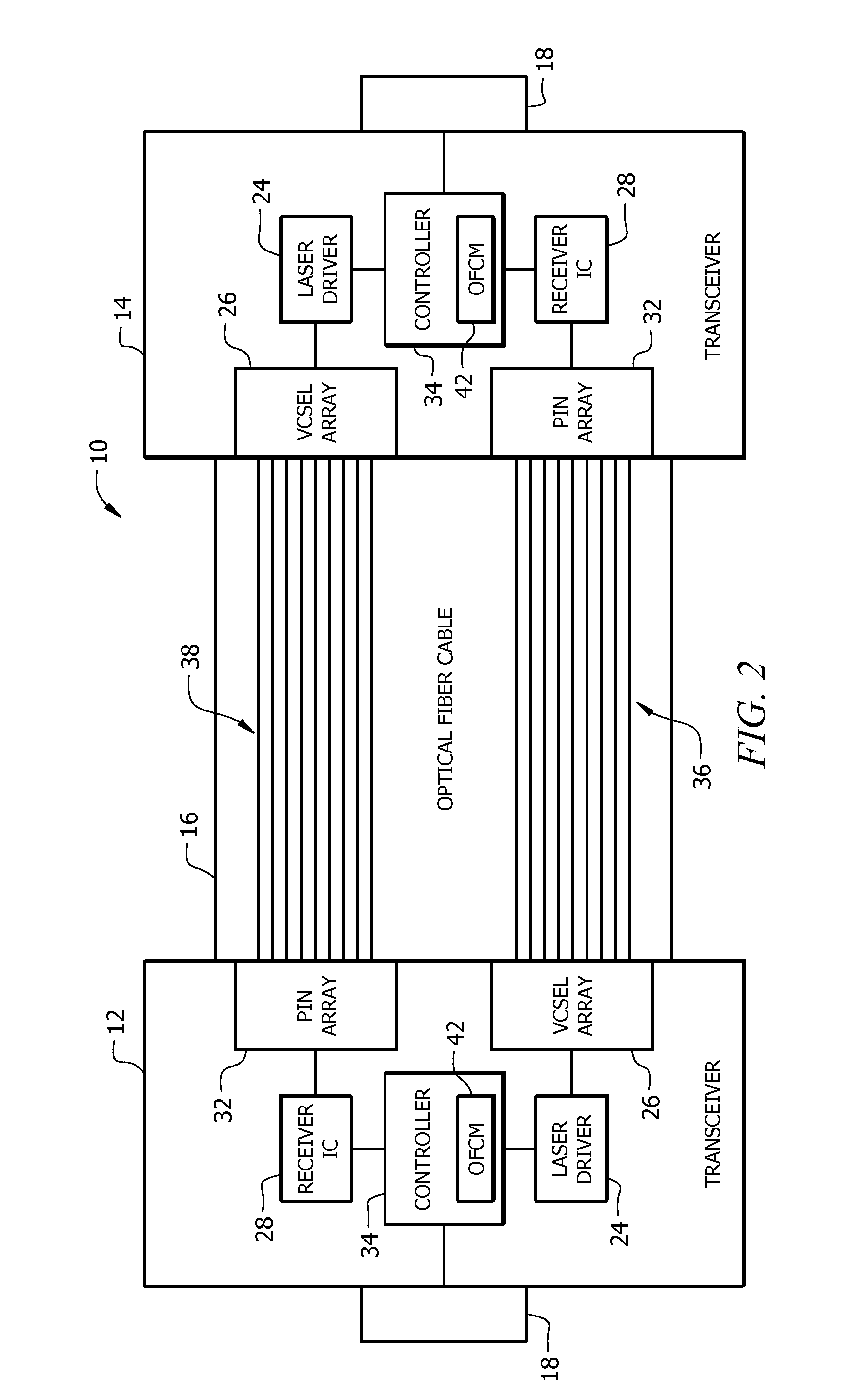
[0016]Embodiments of the invention include an active optical cable having the ability to detect signal loss, e.g., due to fiber breakage, within the active optical cable, and to prevent excessive laser emission from the fiber breakage that is accessible by human eye. The active optical cable includes an open fiber control (OFC) module or other appropriate arrangement configured to detect fiber breakage based on the level of optical power re...


PUM


Abstract

Embodiments of the invention include an active optical cable and method for controlling the operation of the active optical cable based on the detection of signal loss, e.g., due to fiber breakage, within the active optical cable. The active optical cable includes first and second optical transceivers, each with an open fiber control module coupled between the transmission side and the receiver side of the respective optical transceiver. The transmission side of each optical transceiver is coupled to the receiver side of the other optical transceiver via a plurality of transmission channels, such as a plurality of optical fibers. Each open fiber control module is configured to detect an optical power level of an optical signal received by the receiver side of the optical transceiver within which the open fiber control module resides and, based on such detection, control the operation of the corresponding transmission side of the optical transceiver.

Description

BACKGROUND OF THE INVENTION[0001]1. Field of the Invention[0002]The invention relates to active optical cables and systems including active optical cables. More particularly, the invention relates to active optical cable apparatus and methods that detect fiber breakage in an active fiber cable and reduce laser emissions resulting from the fiber breakage.[0003]2. Description of the Related Art[0004]Active optical cables increasingly are being used as an alternative to copper-based connector links, e.g., for data computing connections having data transmission requirements of 10 gigabit (Gbit) per second (Gbit / sec) or more. Conventionally, passive and active copper cabling has provided much of the connectivity between server-to-server and server-to-switch connections in many data computing systems. However, as data transmission rates approach 10 Gbit / sec, the data transfer qualities of copper cabling begins to suffer. Therefore, alternative connectivity solutions, such as active optica...

Claims


Application Information

Patent Timeline
IPC IPC(8): H04B10/08
CPCG01M11/33
Inventor WANG, XIAOZHONGCHAM, KIT MAN
Owner AVAGO TECHNOLOGIED FIBER IP SINGAPORE PTE LTD
Why Eureka
Try Eureka