Optical tracking vehicle control system and method

a technology of vehicle control system and optical tracking, applied in the direction of process and machine control, distance measurement, instruments, etc., can solve the problems of vehicle location and other factors that affect and the rate of gnss satellite reception is relatively low, so as to increase the accuracy of gnss location readings

Active Publication Date: 2011-01-20
AGJUNCTION
View PDF111 Cites 56 Cited by
  • Summary
  • Abstract
  • Description
  • Claims
  • Application Information

AI Technical Summary

Benefits of technology

[0037]A number of “Ground Based Augmentation Systems” (GBASs) also exist which help to increase the accuracy of GNSS location readings by taking additional readings from beacons located at known

Problems solved by technology

These systems suffered from limitations in that signals from the constellation of GNSS satellites are received at a relatively low rate, meaning that the location of the vehicle was also determined from the GNSS system at a relatively low rate.
Accordingly, the vehicles would often deviate from the desired path of travel.
Unfortunately, inertial sensors such as accelerometers and gyroscopes suffer from time-varying errors.
Although this system allows for accurate vehicle positioning and sound

Method used


Image

  • Optical tracking vehicle control system and method
  • Optical tracking vehicle control system and method
  • Optical tracking vehicle control system and method

Examples


Embodiment Construction

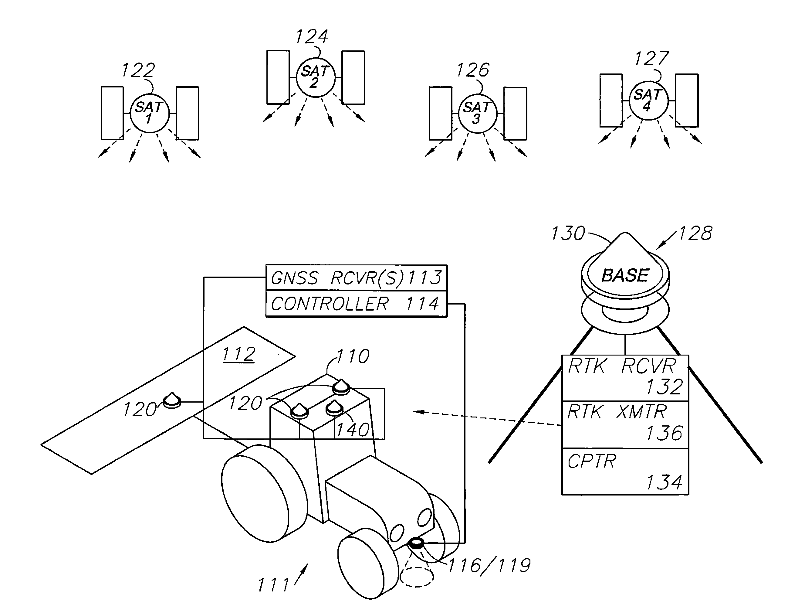
[0062]As required, detailed embodiments of the present invention are disclosed herein; however, it is to be understood that the disclosed embodiments are merely exemplary of the invention, which may be embodied in various forms. Therefore, specific structural and functional details disclosed herein are not to be interpreted as limiting, but merely as a basis for the claims and as a representative basis for teaching one skilled in the art to variously employ the present invention in virtually any appropriately detailed structure.

[0063]Certain terminology will be used in the following description for convenience in reference only and will not be limiting. For example, up, down, front, back, right and left refer to the invention as oriented in the view being referred to. The words “inwardly” and “outwardly” refer to directions toward and away from, respectively, the geometric center of the embodiment being described and designated parts thereof. Global navigation satellite systems (GNS...


PUM


Abstract

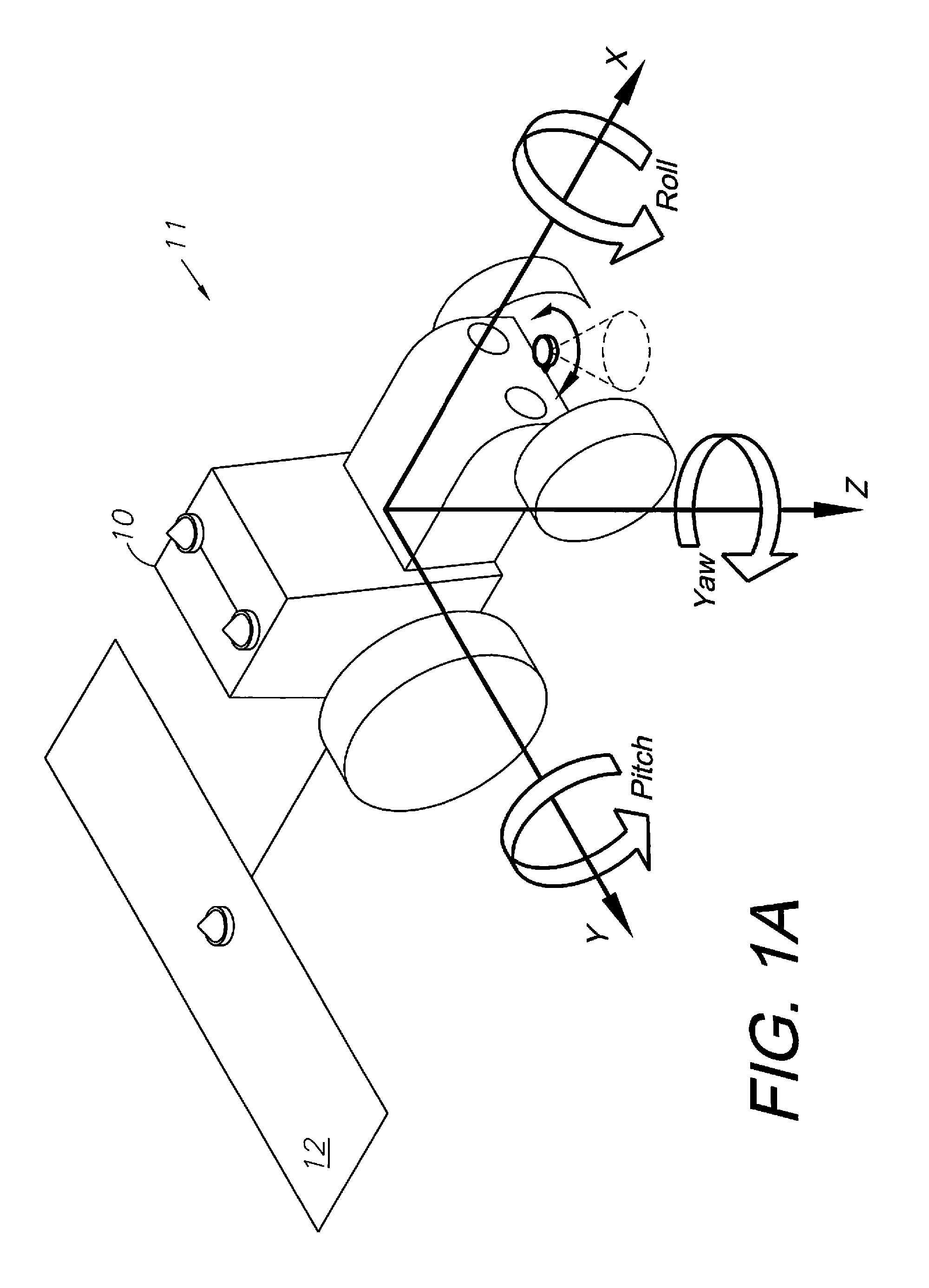
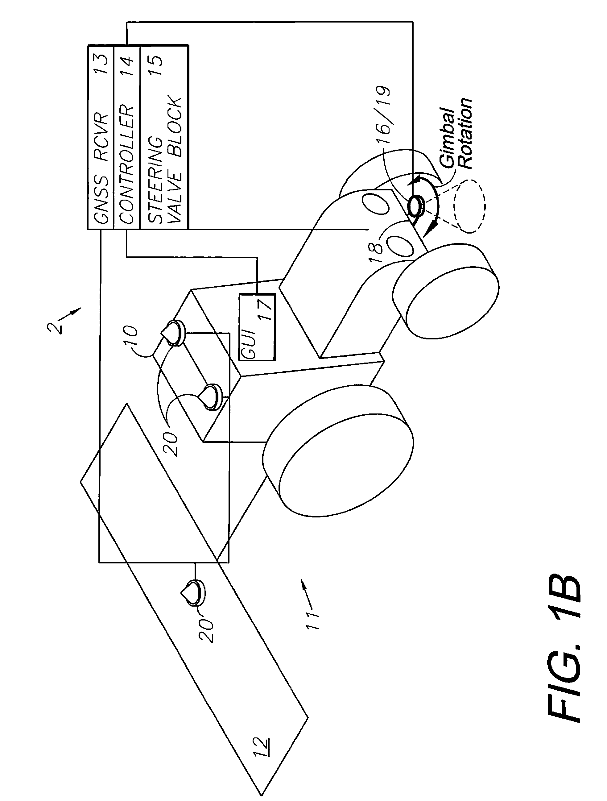
An optical tracking vehicle control system includes a controller adapted for computing vehicle guidance signals and a guidance subsystem adapted for receiving the guidance signals from the controller and for guiding the vehicle. An optical movement sensor is mounted on the vehicle in optical contact with a travel surface being traversed by the vehicle. The optical movement sensor is connected to the controller and provides vehicle movement signals thereto for use by the controller in computing vehicle position. The optical movement sensor can be either mounted on a gimbal for movement independent of the vehicle, or, alternatively, multiple optical movement sensors can be provided for detecting yaw movements. GNSS and inertial vehicle position tracking subsystems are also provided. Still further, a method of tracking a vehicle with an optical movement sensor is provided.

Description

BACKGROUND OF THE INVENTION[0001]1. Field of the Invention[0002]The present invention relates generally to a vehicle control system and method using optical tracking, and in particular to such a system and method for an agricultural vehicle including a towed component comprising an implement.[0003]2. Description of the Related Art[0004]Automatic control of steering (“autosteering”) of vehicles is becoming more widespread, especially in agricultural and mining applications. Most commercially available automatic steering systems include a controller that has means for determining, among other things, the position and heading of a vehicle, a computer-based system for comparing the position and heading of the vehicle with a desired position and heading, and a steering control responsive to a control signal issued by the controller when the position and / or heading of the vehicle deviates from the desired position and / or heading.[0005]As used herein, “attitude” generally refers to the hea...

Claims


Application Information

Patent Timeline
IPC IPC(8): G05D1/00G01S19/43G01S19/54
CPCG01S19/43G05D1/0231G05D2201/0201G05D1/0272G05D1/0278G05D1/027
Inventor REEVE, DAVID R.
Owner AGJUNCTION
Why Eureka
Try Eureka