Parallel processing architecture of flash memory and method thereof

a processing architecture and parallel processing technology, applied in the field of data processing architecture and method thereof, can solve the problems of reducing and achieve the effect of increasing the accessing speed of flash memory

Inactive Publication Date: 2011-01-20
GENESYS LOGIC INC
View PDF3 Cites 15 Cited by
  • Summary
  • Abstract
  • Description
  • Claims
  • Application Information

AI Technical Summary

Benefits of technology

[0004]One objective of the present invention is to provide a parallel processing architecture and method thereof for performing a plurality of commands and processing multiple input / output data streams during a time interval to increase the accessing speed of the flash memory.

Problems solved by technology

That is, during a time interval, the controller only performs a command and processes a data stream but cannot perform a plurality of commands and process multiple input / output data streams.
Thus, accessing speed of the flash memory is restricted considerably.
Therefore, the unit of writing step is inconsistent with the unit of erasing step, resulting in decreasing the accessing speed of the flash memory.

Method used


Image

  • Parallel processing architecture of flash memory and method thereof
  • Parallel processing architecture of flash memory and method thereof
  • Parallel processing architecture of flash memory and method thereof

Examples


first embodiment

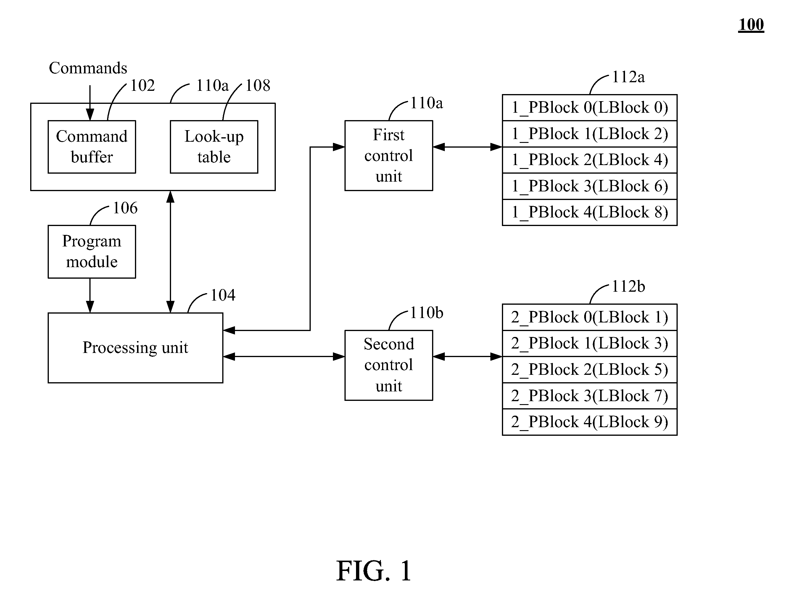
[0021]FIG. 1 is a schematic view of a parallel processing architecture 100 of flash memory according to the present invention. The parallel processing architecture 100 includes a command buffer 102, a processing unit 104, a program module 106, a look-up table 108, a first control unit 110a, a second control unit 110b, a first memory unit 112a and a second memory unit 112b. The command buffer 102, the look-up table 108 and the application module 106 are coupled to the processing unit 104, respectively. The processing unit 104 is coupled to the first control unit 110a and the second control unit 110b, respectively. The first control unit 110a and the second control unit 110b are coupled to the first memory unit 112a and the second memory unit 112b, respectively. In one embodiment, the command buffer 102 and the look-up table 104 are positioned in the random access memory (RAM), e.g. dynamic random access memory (DRAM), static random access memory (SRAM), and / or various types of memory...

second embodiment

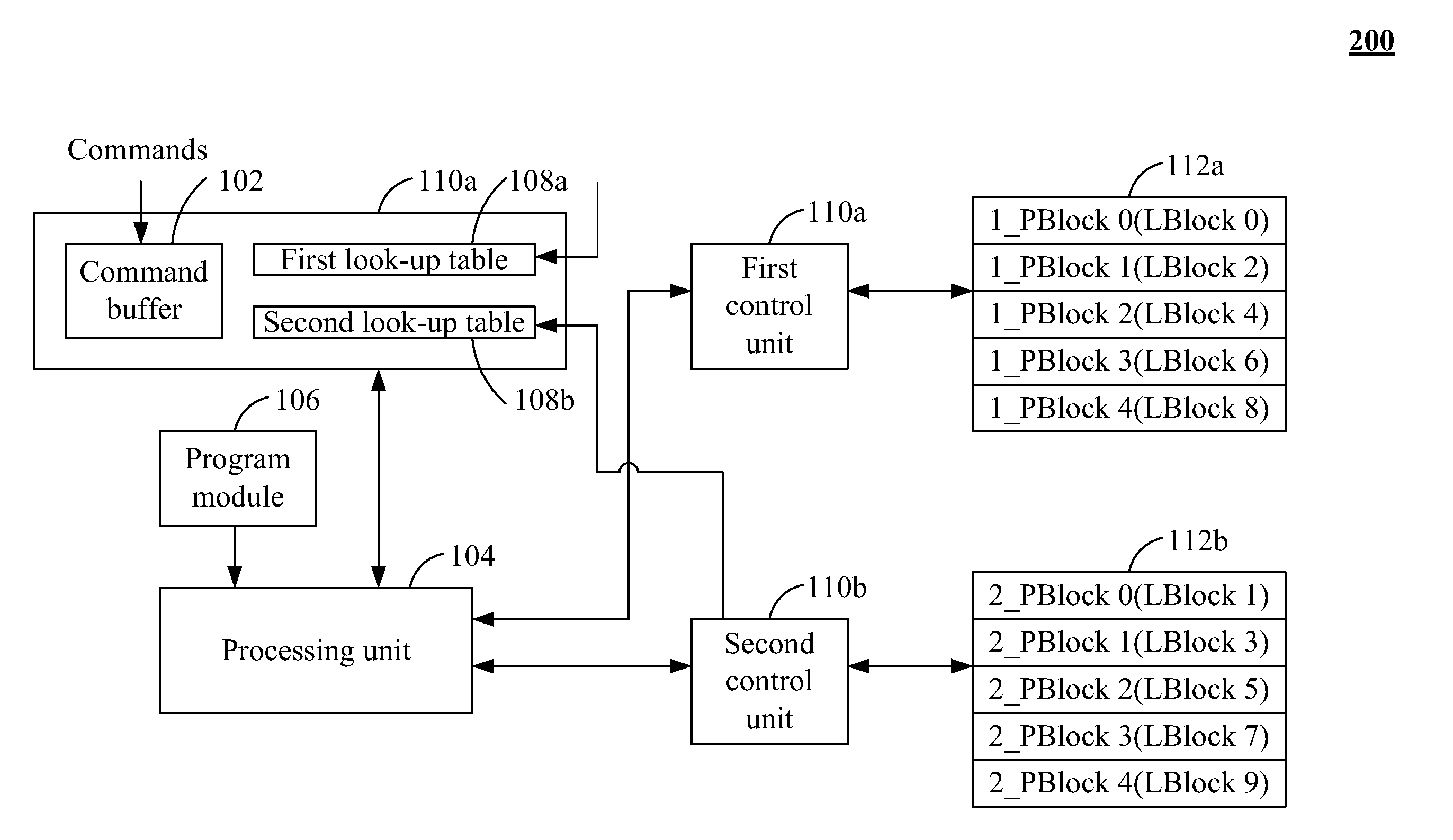
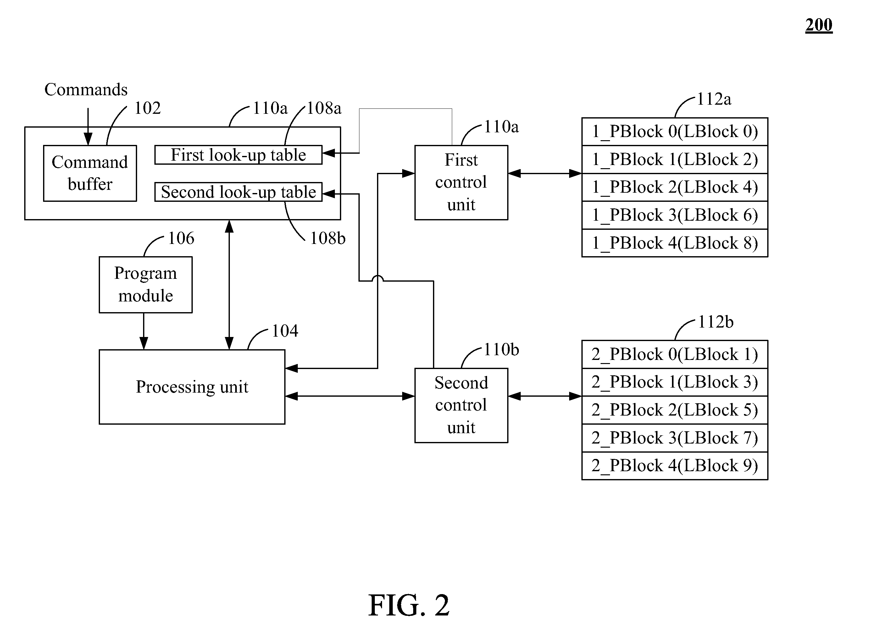
[0026]FIG. 2 is a schematic view of a parallel processing architecture 200 of flash memory according to the present invention. The parallel processing architecture 200 in FIG. 2 is similar to the parallel processing architecture 100 in FIG. 1. The difference is that the look-up table 108 in FIG. 1 is replaced with the first look-up table 108a and the second look-up table 108b in FIG. 2. The first look-up table 108a is coupled to the processing unit 104 and stores the corresponding relationship between the first logical address blocks of the data. The second look-up table 108b is coupled to the processing unit 104 and stores the corresponding relationship between the second logical address blocks of the data and the second physical blocks. The processing unit 104 utilizes the first look-up table 108a and the second look-up table 108b to classify the commands based on the first logical address blocks and the second logical address blocks. The first control unit 110a utilizes the first...


PUM


Abstract

A parallel processing architecture of flash memory and method thereof are described. A processing unit classifies a plurality of commands to generate a first command group and a second command group respectively. The processing unit executes the first command group and the second command group. A first control unit performs the first command group to access the data stored in the first memory unit, and a second control unit simultaneously performs the second command group to access the data stored in the second memory unit for processing the data stored in the first and the second memory units in parallel.

Description

CLAIM OF PRIORITY[0001]This application claims priority to Taiwanese Patent Application No. 098124229 filed on Jul. 17, 2009.FIELD OF THE INVENTION[0002]The present invention relates to a data processing architecture and method thereof, and more particularly relates to a parallel processing architecture and method thereof for flash memory.BACKGROUND OF THE INVENTION[0003]With the rapid development of flash memory, more and more electronic products are equipped with flash memory to be served as storage media. For an example of NAND (Not AND) flash memory, when applying to version 2.0 or prior versions of Universal Serial Bus (USB) protocol, one controller is utilized to control one chip of NAND flash memory. However, version 2.0 or prior versions of USB protocol only supports one command and a data stream for processing the data stored in the flash memory. That is, during a time interval, the controller only performs a command and processes a data stream but cannot perform a pluralit...

Claims


Application Information

Patent Timeline
Patent Type & Authority Applications(United States)
IPC IPC(8): G06F12/02G06F12/00
CPCG06F2212/7208G06F12/0246
Inventor LIN, JIN-MINHWANG, WEI-KAN
Owner GENESYS LOGIC INC
Why Eureka
Try Eureka