Defibrillation system

a technology of defibrillation system and electrode, which is applied in the direction of heart defibrillator, external electrode, therapy, etc., can solve the problems of affecting the amount of time that the electrodes can be worn by a patient, and achieve the effect of minimizing the electrode area, effective defibrillation, and improving the long-term wearability of the system

Inactive Publication Date: 2011-01-27
ZOLL MEDICAL CORPORATION
View PDF24 Cites 235 Cited by
  • Summary
  • Abstract
  • Description
  • Claims
  • Application Information

AI Technical Summary

Benefits of technology

[0010] By monitoring the patient for patient information and switching the plurality of capacitors in accordance with the patient information, the foregoing aspect of the invention makes it possible to deliver, to the patient, defibrillation energy which is appropriate for that patient. As a result, the invention provides increased effectiveness in the treatment of cardiac arrhythmias.
[0035] In another embodiment, long term wear can be enhanced and skin irritation reduced by including in the system means for monitoring, and adjusting as necessary, the environment at the interface between the electrode array and the skin. Such means may include, for example, means for monitoring and adjusting the {PH at the skin-electrode interface in order to maintain a neutral non-irritating interface; and means for controlling the ion flow at the interface between the electrodes and the skin. In the latter embodiment, ion flow would be reduced to a minimum except for the short time during which a defibrillating shock is being delivered, at which time the ion flow would temporarily increase to provide a conductive path for the defibrillation impulse.

Problems solved by technology

Also, the size, configuration, and materials used to construct the electrodes contribute the amount of time that the electrodes can be worn by a patient.

Method used


Image

  • Defibrillation system
  • Defibrillation system
  • Defibrillation system

Examples


Embodiment Construction

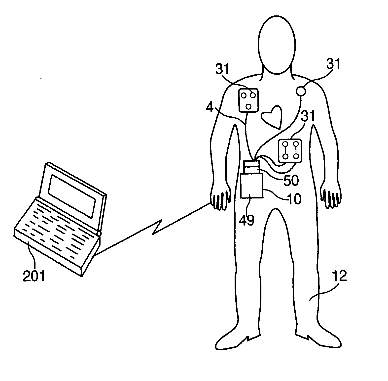
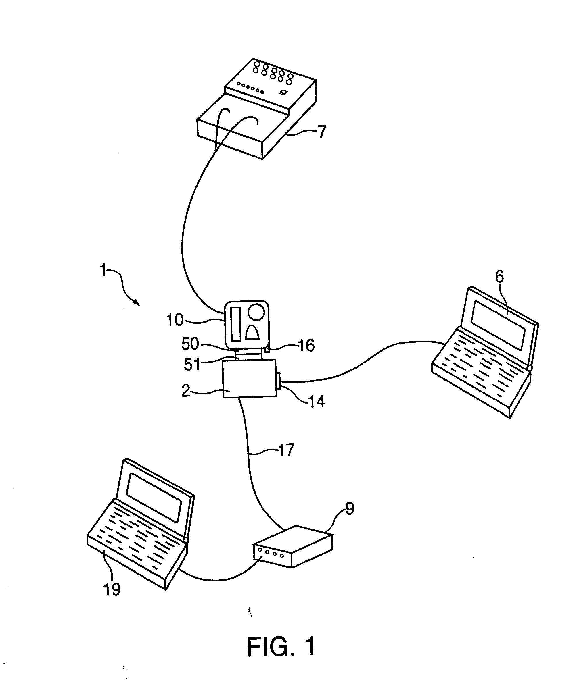
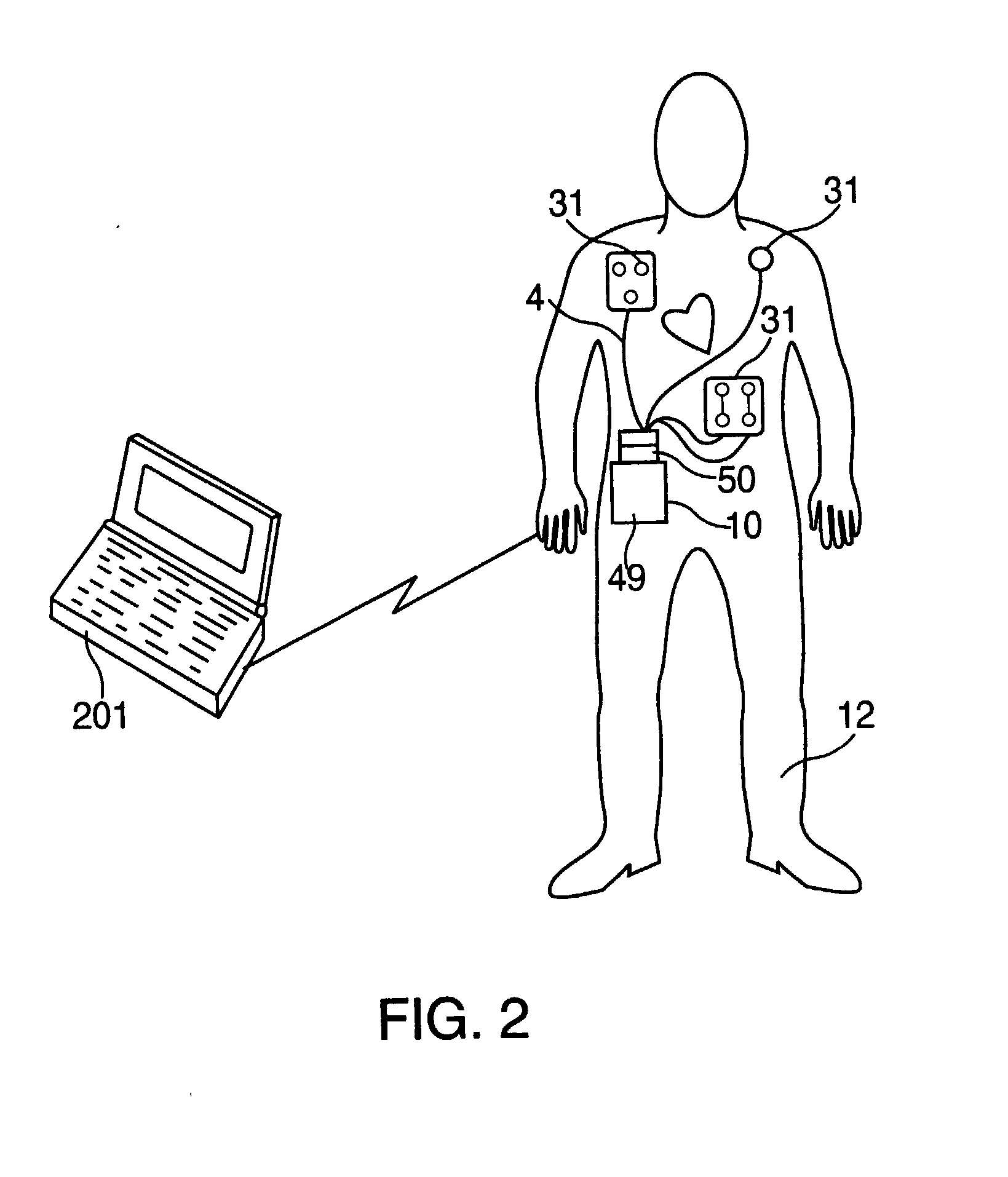
[0062] The present invention is directed to a defibrillation system for use in treating patients who have suffered from cardiac arrhythmias. A representative embodiment of the invention is shown in FIGS. 1 and 2. As shown in these figures, defibrillation system 1 is comprised of base station 2, electrode harness 4, personal computer 6, patient simulator 7, central repository 9, and wearable defibrillator 10. A brief overview of the operation of each of these components is provided below, followed by detailed descriptions thereof.

[0063] Defibrillator 10 is capable of interfacing either to base station 2, as shown in FIG. 1, or to electrode harness 4, as shown in FIG. 2. To this end, both electrode harness 4 and base station 2 include physical connector identifiers at their respective interfaces to defibrillator 10. By reading these connector identifiers, defibrillator 10 is able to determine both the type of interfaced device (i.e., a base station or electrode harness) and the ident...


PUM


Abstract

A method of treating a patient for ventricular tachycardia using a wearable defibrillator includes monitoring the patient for a predetermined condition via one or more electrodes on the defibrillator, sending a message to the patient in response to the predetermined condition, activating the defibrillator so that the defibrillator delivers defibrillation energy to the patient, and storing at least one of the results of the monitoring, sending and activating steps in a memory on the defibrillator. The method also includes downloading information stored in the memory of the defibrillator to a base station having an external interface, and transmitting the information downloaded from the memory of the base station to an external location via the external interface of the base station.

Description

BACKGROUND OF THE INVENTION [0001] 1. Field of the Invention [0002] The present invention is directed to a defibrillation device, and more particularly to a personal wearable pacer / cardioverter / defibrillator which monitors a patient's condition, detects shockable or paceable arrhythmias, determines consciousness, and, in the case that the patient is determined to be unconscious, administers therapy to the patient. [0003] 2. Description of the Related Art [0004] Cardiac arrhythmias, such as ventricular fibrillation and ventricular tachycardia, are electrical malfunctions of the heart, in which regular electrical impulses in the heart are replaced by irregular, rapid impulses. These irregular, rapid impulses can cause the heart to stop normal contractions, thereby interrupting blood flow therethrough. Such an interruption in blood flow can cause organ damage or even death. [0005] Normal heart contractions, and thus normal blood flow, can be restored to a patient through application of...

Claims


Application Information

Patent Timeline
Patent Type & Authority Applications(United States)
IPC IPC(8): A61N1/39A61N1/04
CPCA61N1/0452A61N1/0456A61N1/046A61N1/0468A61N1/0472A61N1/0476A61N1/3993A61N1/0496A61N1/39A61N1/3918A61N1/3925A61N1/3937A61N1/3987A61N1/0492A61N1/3904
Inventor OWEN, JAMES M.FINCKE, RANDALL W.O'LEARY, JAMES P.TOTMAN, MARK H.
Owner ZOLL MEDICAL CORPORATION
Why Eureka
Try Eureka