Layered interface in an industrial environment

a technology of industrial environment and interface, applied in the field of industrial environment operation, can solve the problems of increasing complexity of the system, affecting and limiting the interoperability and consistency of such products

Active Publication Date: 2011-01-27
ROCKWELL AUTOMATION TECH
View PDF96 Cites 47 Cited by
  • Summary
  • Abstract
  • Description
  • Claims
  • Application Information

AI Technical Summary

Benefits of technology

The following presents a simplified summary in order to provide a basic understanding of some aspects of the subject disclosure. This summary is not an extensive overview, and it is not intended to identify key / critical elements of the subject disclosure or to delineate any scope. The sole purpose of this summary is to present some concepts in a simplified form as a prelude to the more detailed description that is presented later.

Problems solved by technology

As systems have become more complex, however, communications and functional cooperation between components of the industrial automation system has become a challenge.
For instance, when users purchase multiple products from one or more vendors, there is often limited interoperability and consistency between such products.
Limited product and component consistency suggest that techniques engineers learn for one product do not necessarily carry over to other implementations.
Often, integration of products in the industrial automation system is complex and difficult to manage.
Process and control engineers cannot easily code and configure their respective components without concern for other system components, which may have different manufacturers and different platforms.
Another problem with integration of products is that process and control engineers focus on underlying technical details, including implementation and glue logic, rather than the application level concerns, for example process information.
In another case, system design does not sufficiently enable trade-offs between overhead burden (memory footprint, CPU cycles, and so forth) and application coupling.
Current solutions however do not facilitate a smooth and uncomplicated transition for the respective changes.
Multiple technologies underneath many vendors' products complicate configuration and management of systems.
Such complexity hinders the system's capacity to provide higher-level information and can reduce the ability to configure such systems.

Method used


Image

  • Layered interface in an industrial environment
  • Layered interface in an industrial environment
  • Layered interface in an industrial environment

Examples


embodiment 800

FIG. 8 represents example embodiments of a layer in an industrial environment in accordance with aspects of the subject disclosure. In embodiment 800, layer 810 includes a set of M layers 8141-814M, with M a natural number equal to or greater than unity (1); each of these layers can be referred to as a sub-layer of layer 810. Each sub-layer 814γ, with γ=1, 2 . . . M, includes a set of one or more interface component(s) 816γ. Communication interface(s) 818 can include network adaptor(s), port(s), reference link(s), or the like, and enables communication amongst two or more of sub-layers 8141-814M. The group of sets of one or more interface component(s) 8161-816M corresponds to a set of one or more interface component(s). In an example scenario in which layer 810 embodies layer 7101, the set of one or more interface(s) 8161-816M compose the set of one or more interface component(s) 7141. Layer 810 can embody one or more of layers 7101-710N, or any layer within a referred to in the sub...

embodiment 850

As illustrated in embodiment 850, a layer 860 can include a physical layer 864 and a logical layer 868. Each of such layers also can be decomposed, or arranged, in sub-layers: Physical sub-layers and logical sub-layers. Both physical sub-layers and logical sub-layers can be ordered according to complexity, as described supra.

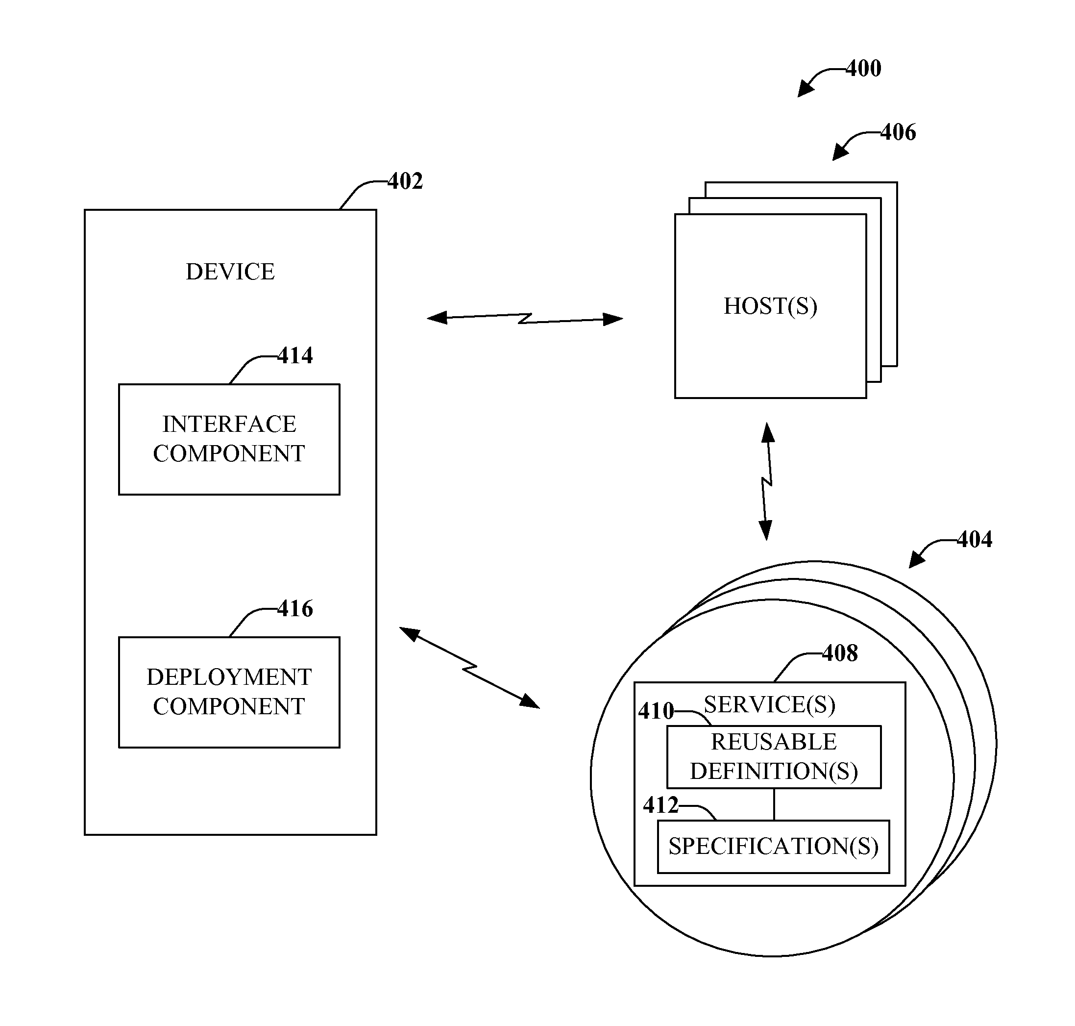
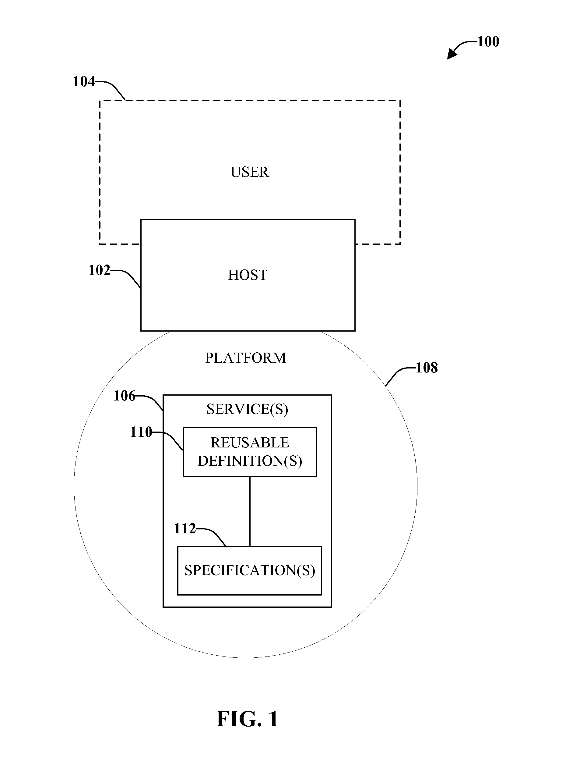
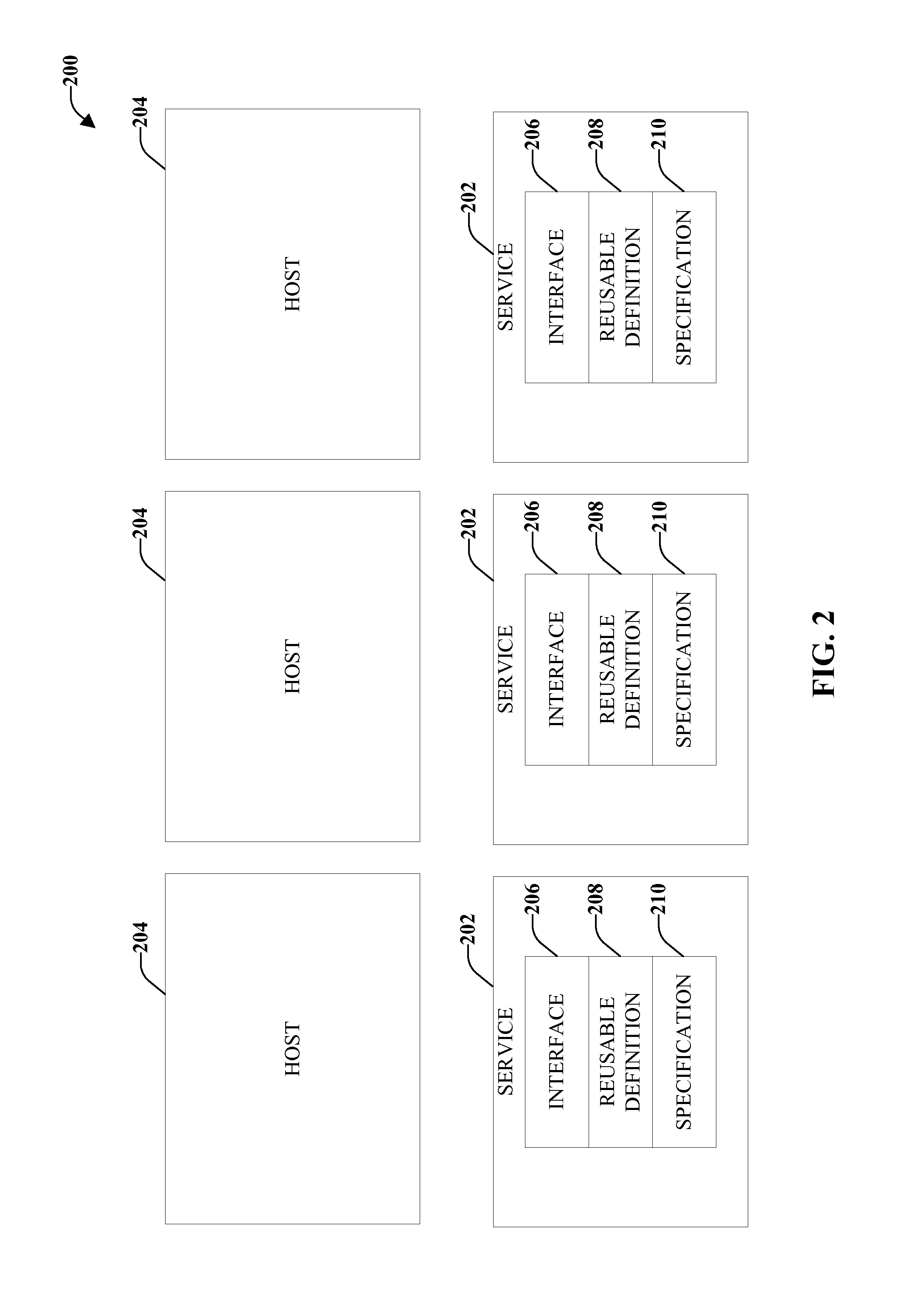
FIG. 9 is a block diagram of an example embodiment 900 of a layer in accordance with aspects of the subject disclosure. Layer 910 embodies one or more of layers 710κ or 814γ, or any other layer described herein. Layer 910 includes an implementation platform 914 that instantiates an interface component of a group of one or more interface component(s) 918. In an aspect, to instantiate the interface component implementation platform 914 can acquire interface component and, based at least on information (data, metadata, etc.) related to the functionality of the interface component, generate a service configured to implement the interface component and functionality ...

embodiment 1000

In certain embodiments, implementation platform 914 can acquire an interface component from a disparate layer (not shown) or from a centralized network node (e.g., a host) that is part of an industrial environment that includes layer 910. In other embodiments, implementation platform 914 can acquire an interface component from a specific portion of layer 910. For instance, in a scenario in which layer 910 is a control layer, implementation platform 914 can acquire the interface component from a controller installed in a specific part of plant or factory. In an example embodiment, e.g., embodiment 1000 presented in FIG. 10, implementation platform 914 includes an acquisition component 1016 that can access (retrieve, receive, etc.) a specification that defines an interface component. Acquisition component 1016 can retain the specification (not shown) in repository 922. Acquisition component 1016 also can convey such specification.

In addition, in certain embodiments such as example emb...


PUM


Abstract

System(s) and method(s) are provided for implementing a set of interface components across a set of layers of an industrial environment, and for managing at least one interface component or at least one layer of the industrial environment. To implement an interface component in at least one layer in the set of layers, a specification that defines the interface component is acquired and, based at least on the specification, a service is generated. Execution of the service implements the interface component. The managing includes deploying or discovering the at least one interface component or the at least one layer of the industrial environment. The managing also includes indexing specific functional feature(s) of the at least one interface component and searching across the set of layers for one or more interface components that satisfy specific functional criteria. Moreover, the managing can include supplying metadata related to interface component(s) or layer(s).

Description

TECHNICAL FIELDThe subject disclosure relates generally to operation of an industrial environment and, more specifically, to implementing a set of interface components across a set of layers of the industrial environment and to managing at least one interface component or at least one layer of the industrial environment.BACKGROUNDIndustrial control systems can employ complex mechanical, electronic, electro-mechanical, and / or robotic machinery to perform various automated mechanical and / or electrical functions. Examples of machinery include industrial motors, pumps, conveyors, escalators, drills, refrigeration systems, and so forth. An industrial control system can utilize one or more control devices to activate or deactivate the machinery and / or to determine an appropriate level of activation for the machinery (e.g., an amount of current to supply to a variable input motor). Additionally, the control devices can be associated with logical program code that determines an appropriate ...

Claims


Application Information

Patent Timeline
Patent Type & Authority Applications(United States)
IPC IPC(8): G05B19/42
CPCG05B19/0426G05B19/056G05B19/41845G05B2219/36174G05B2219/23389G05B2219/32137G05B2219/13063Y02P90/02Y02P90/80
Inventor PLACHE, KENNETHSEGER, III, DANIEL B.STARON, RAYMONDKRETSCHMANN, ROBERT J.JASPER, TARYLJARRETT, JAMES HARRYBRANDES, RUSSELLBLISS, RONALDKALAN, MICHAELGOVINDARAJ, SUBBIANHALL, KENWOODREICHARD, DOUGLAS J.
Owner ROCKWELL AUTOMATION TECH
Why Eureka
Try Eureka