

Pump of energy and volatile materials
Inactive Publication Date: 2011-02-03
KAZADI SANZA T +1
View PDF5 Cites 2 Cited by
- Summary
- Abstract
- Description
- Claims
- Application Information
AI Technical Summary
Benefits of technology
[0024]Accordingly, transferring energy according to this methodology from one point to another has several benefits. First, molecular carriers moving energy from one point to another through an insulated tube transfer little or no energy to the outside world in any form, including electromagnetic waves, thermal pollution, or noise. Depending on the carrier chosen, such a transfer mechanism can remain safe in the event of a breach caused by an act of Man or Nature; the release of such a molecular carrier into the atmosphere can have little or no environmental impact. Finally, the transfer inefficiencies, which can be the limiting factors, can be extremely small even over great distances.
[0025]As the molecular carrier is transported via diffusion through a heated conduit, no thermal energy transfer to the conduit from the molecular carrier vapor is possible; the vapor passes through the conduit without condensing or refluxing. As a result, the characteristic distance k is essentially infinite, making the transport of the vapor over long distances, both vertically and horizontally, possible. As a result, the method can be used to transport liquids and solids vertically within skyscrapers, over mountainous regions, and over very long horizontal distances. The transport can happen at very high speeds due to the speed of diffusion of the vapor state, and can therefore allow for rapid delivery as compared to the same in a liquid state.
[0027]The second major advantage is the transfer of materials through the same method without the requirement of having moving parts or specialized materials. This advantage makes the device simple and cheap to make, extremely durable over a long period of time, and capable of functioning in nearly any environment. The capital investment and subsequent maintenance are extremely low in comparison to mechanical pumps which require relatively frequent service and part replacement. Depending on the combination of pumped material and pump material, the device might last for upwards of one hundred years without repair.
Problems solved by technology
First, molecular carriers moving energy from one point to another through an insulated tube transfer little or no energy to the outside world in any form, including electromagnetic waves, thermal pollution, or noise.
Finally, the transfer inefficiencies, which can be the limiting factors, can be extremely small even over great distances.
Method used
View moreImage
Smart ImageViewing Examples

Examples
third embodiment
[0046]A third embodiment illustrated in FIG. 3 has solar reflectors (27) providing heating of the energy conduit.
fourth embodiment
[0047]A fourth embodiment illustrated in FIG. 4 has an in-line generator (23) inserted between the energy conduit and the condenser. This allows fast-moving vapor to be used to generate electricity.
fifth embodiment
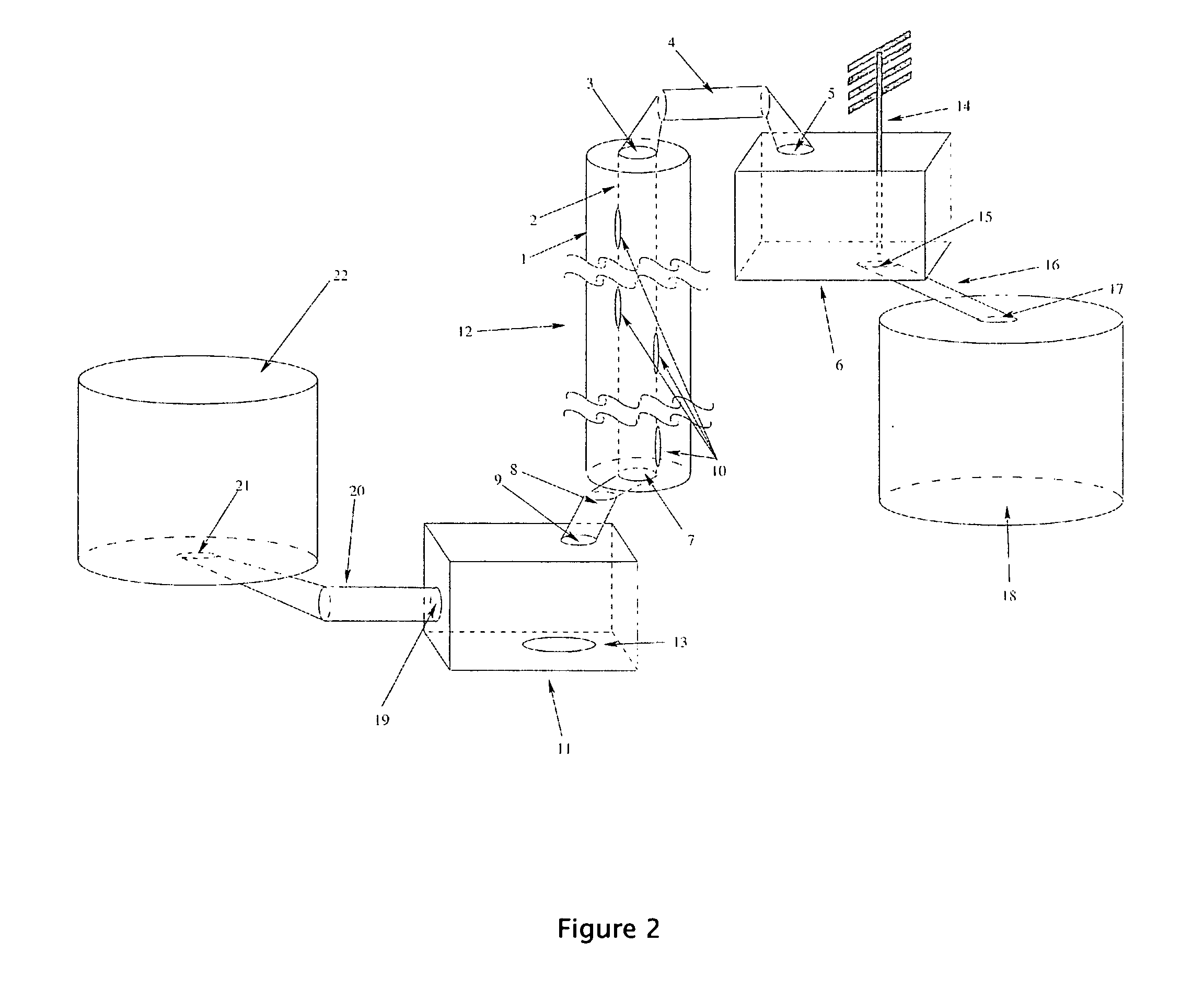
[0048]A fifth embodiment illustrated in FIG. 4 has an in-line generator (23) inserted between the energy conduit and the condenser. This allows fast-moving vapor to be used to generate electricity. Moreover, this embodiment has a fluid return conduit (25) connecting the condenser and the vaporizer which allows collected fluid to return to the vaporizer once it has been condensed in the condenser.
Login to View More PUM
 Abstract
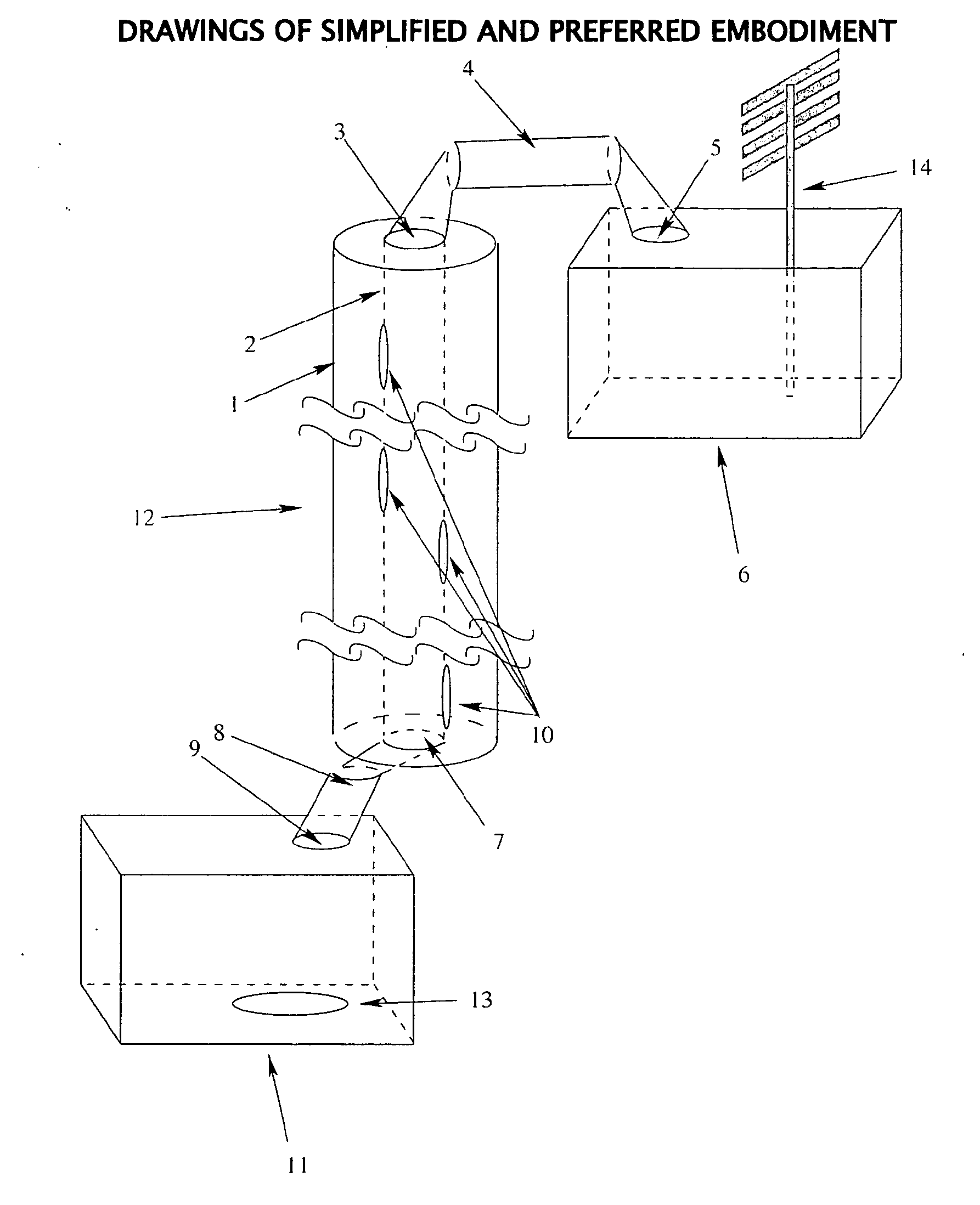
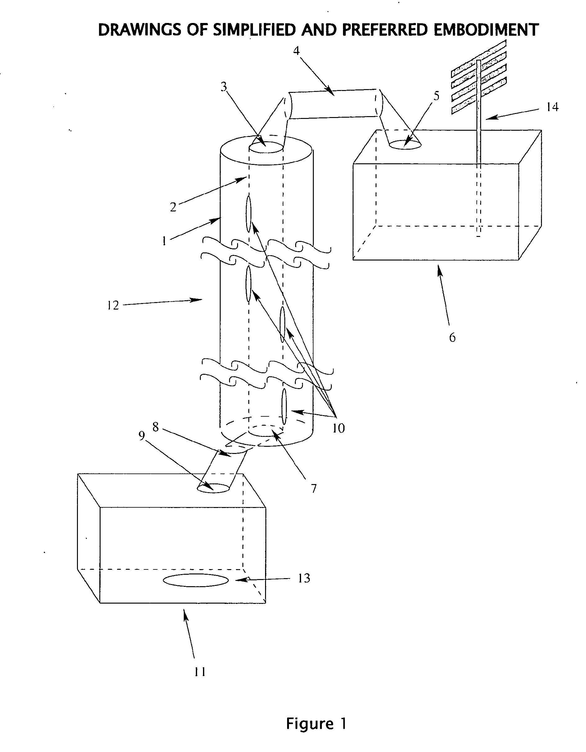
A pump is provided which pumps energy via molecular carriers; the side effect of this method of energy transmittance is the concomitant movement of material. The method of energy and material movement follows three steps. In step one, energy is absorbed by the molecular carrier, transforming the carrier from a liquid or solid state into a gaseous state. The second step is the conveyance of the energized molecular carriers through an energy conduit, through which the molecular carriers may pass without losing energy, despite a potentially very long distance. The third step involves deposition of the energy at the final destination via a transfer which extracts the energy from the material, concomitantly transforming the material from a gaseous state to a liquid or solid state.
Description
FIELD OF THE INVENTION[0001]This invention relates to the field of transport of both energy and volatile materials over short or long distances. Note that many materials are volatile under some conditions which do not induce volatility in other materials. The current invention is capable of working in a variety of conditions (temperature, pressure, etc.) ensuring that while some of these conditions do not result in the capacity to pump specific materials, the pump can be used in other sets of conditions which do result in pumping capacity for the same materials (ex. metallic sodium may be pumped in the current invention at high temperatures).SUMMARY OF THE PRIOR ARTCitations:[0002]4,038,972Solar energy collection apparatusOrrison4,143,644Apparatus for producing useful heat from solarHeitlandradiation4,429,213Electrically heated fluid conduitMathieu4,749,447Evacuated evaporation-pressurizedLewcondensation solar still5,511,954Water pumping system using solar energyHan5,178,734Water di...
Claims
Login to View More Application Information
Patent Timeline
 IPC IPC(8): F01K25/08
CPCF22B1/284F01K27/00
InventorKAZADI, SANZA T.WEBB, MARK
OwnerKAZADI SANZA T