System and method for supplying fuel to a gas turbine

Inactive Publication Date: 2011-02-03
GENERAL ELECTRIC CO
View PDF9 Cites 19 Cited by
  • Summary
  • Abstract
  • Description
  • Claims
  • Application Information

AI Technical Summary

Benefits of technology

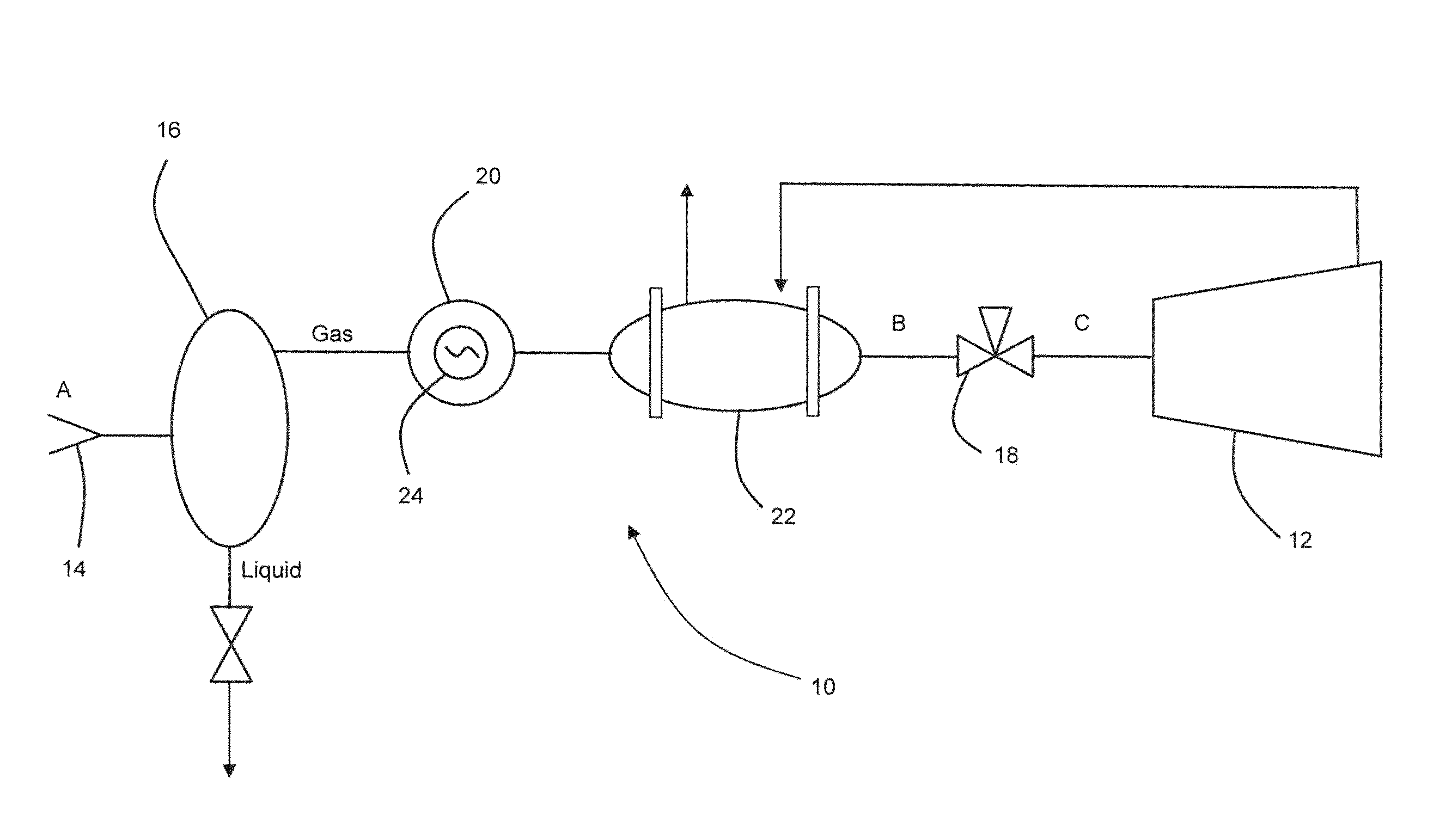
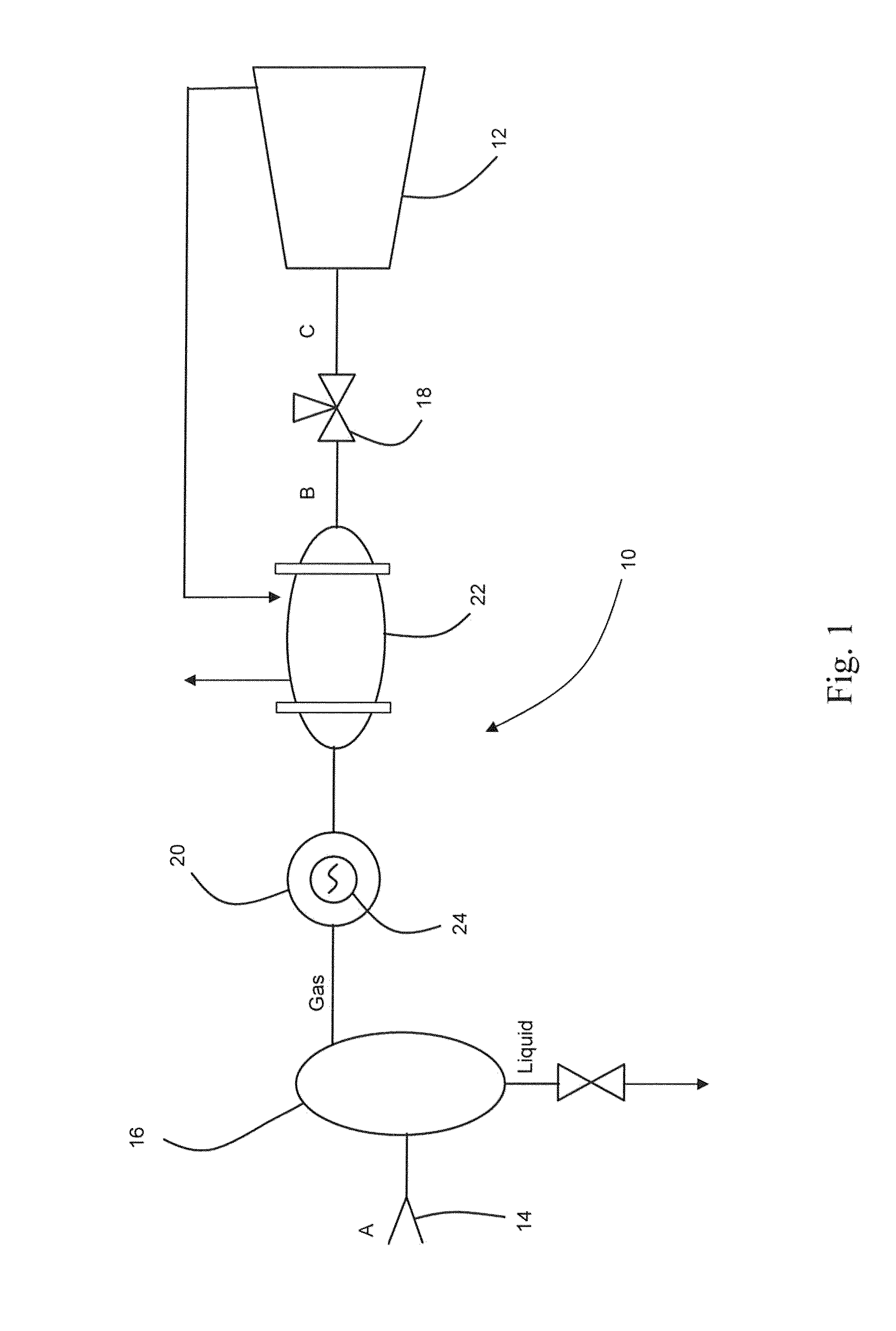
[0010]One embodiment of the present invention is a system for supplying fuel to a gas turbine. The system includes piping that contains a supply of fuel at a pressure greater than approximately 500 pounds per square inch. Means for reducing the pressure of the supply of fuel is connected downstream of the piping to reduce the pressure of the supply of fuel to less than approximately 200 pounds per square inch. A separator is connected downstream of the means for reducing the pressure of the supply of fuel, and the separator includes a gaseous port and a liquid port. A control valve is connected to the gaseous port, and the control valve reduces the pressure of the supply of fuel to produce a superheated fuel having a pressure of less than approximately 50 pounds per square inch.
[0011]In another embodiment of the present invention, a system for supplying fuel to a gas turbine includes piping that contains a supply of fuel at a pressure greater than approximately 500 pounds per square inch. A pressure reducing valve is connected downstream of the piping, and the pressure reducing valve is configured to reduce the pressure of the supply of fuel to less than approximately 200 pounds per square inch. A heat exchanger is connected downstream of the pressure reducing valve to heat the supply of fuel. A control valve is connected downstream of the heat exchanger, and the control valve reduces the pressure of the supply of fuel to less than approximately 50 pounds per square inch.
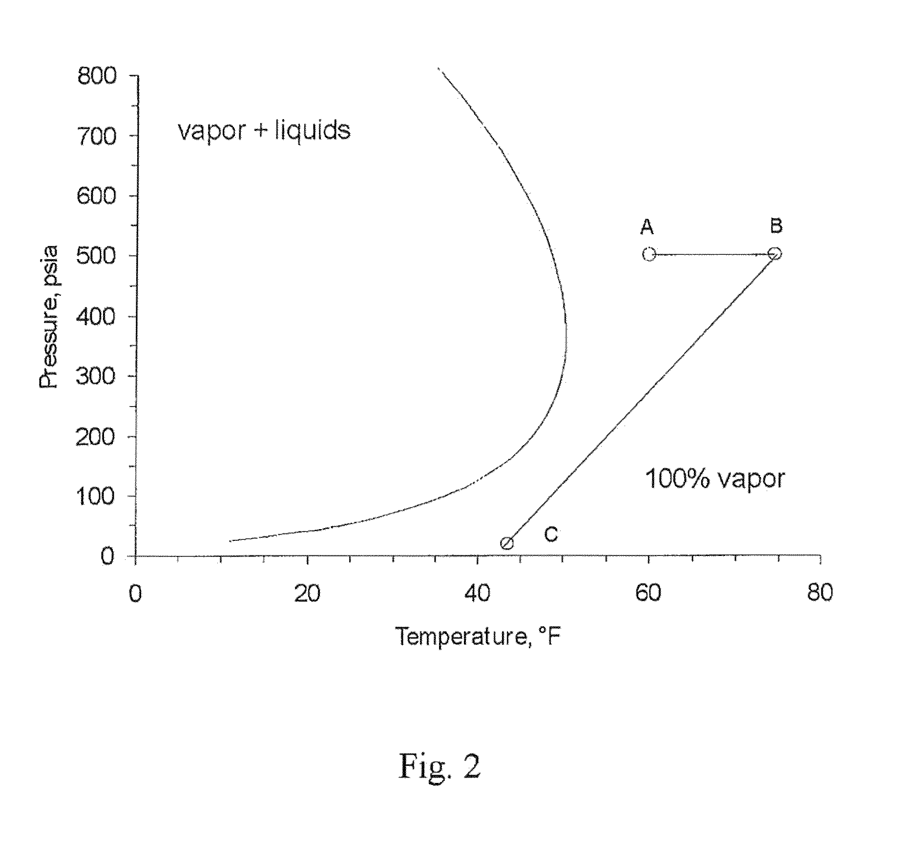
[0012]The present invention further includes a method for supplying superheated fuel to a gas turbine. The method includes receiving a supply of fuel having a pressure greater than approximately 500 pounds per square inch and reducing the pressure of the supply of fuel to less than approximately 200 pounds per square inch to produce a wet saturated fuel having a mixture of gaseous fuel and liquid fuel. The method further includes separating the gaseous fuel from the liquid fuel, reducing the pressure of the gaseous fuel to less than approximately 50 pounds per square inch to produce a superheated fuel, and flowing the superheated fuel to the gas turbine.

Problems solved by technology

Liquids from condensed gases in the fuel produce serious detrimental effects in the combustors that may result in hardware damage.
However, during startup operations, heat is not readily available from the gas turbine 12, thus requiring a second heat exchanger 20 with an independent heat source 24.
The need for a second heat exchanger with an independent heat source to supply heat during start up operations requires additional capital costs in the construction of the gas turbine system.
Moreover, the power consumed by the second heat exchanger to superheat the fuel decreases the overall efficiency of the gas turbine plant.

Method used


Image

  • System and method for supplying fuel to a gas turbine
  • System and method for supplying fuel to a gas turbine
  • System and method for supplying fuel to a gas turbine

Examples


Embodiment Construction

[0019]Reference will now be made in detail to present embodiments of the invention, one or more examples of which are illustrated in the accompanying drawings. The detailed description uses numerical and letter designations to refer to features in the drawings. Like or similar designations in the drawings and description have been used to refer to like or similar parts of the invention.

[0020]Each example is provided by way of explanation of the invention, not limitation of the invention. In fact, it will be apparent to those skilled in the art that modifications and variations can be made in the present invention without departing from the scope or spirit thereof. For instance, features illustrated or described as part of one embodiment may be used on another embodiment to yield a still further embodiment. Thus, it is intended that the present invention covers such modifications and variations as come within the scope of the appended claims and their equivalents.

[0021]FIG. 3 provide...


PUM


Abstract

A system for supplying fuel to a gas turbine includes piping containing fuel at a pressure greater than approximately 500 psi. A pressure reducing valve connected downstream of the piping reduces the pressure of the fuel to less than approximately 200 psi. A heat exchanger connected downstream of the pressure reducing valve heats the wet saturated fuel or dry saturated fuel to produce a superheated fuel. A control valve connected downstream of the heat exchanger reduces the pressure of the superheated fuel to less than approximately 50 psi. A method for supplying superheated fuel to a gas turbine includes receiving fuel having a pressure greater than approximately 500 psi and reducing the pressure to less than approximately 200 psi. The method further includes separating gaseous fuel from liquid fuel, reducing the pressure of the gaseous fuel to less than approximately 50 psi, and flowing the superheated fuel to the gas turbine.

Description

FIELD OF THE INVENTION[0001]The present invention generally involves a gas turbine fuel system. More particularly, the present invention describes a fuel system that can supply superheated gas fuel to a gas turbine.BACKGROUND[0002]Gas turbines are widely used in commercial operations for power generation. Gas turbines generally include a compressor at the front, one or more combustors around the middle, and a turbine at the rear. The compressor progressively compresses a working fluid and discharges the compressed working fluid to the combustors. The combustors inject fuel into the flow of compressed working fluid and ignite the mixture to produce combustion gases having a high temperature, pressure, and velocity. The combustion gases exit the combustors and flow to the turbine where they expand to produce work.[0003]Liquids from condensed gases in the fuel produce serious detrimental effects in the combustors that may result in hardware damage. The fuel supplier typically provides ...

Claims


Application Information

Patent Timeline
IPC IPC(8): F02C7/22G05D11/00
CPCF02C7/224F02C3/22Y10T137/2605
Inventor RENDO, KOREY FREDERICWILKES, COLINMOSS, DANIEL MARTINBILTON, TIMOTHY RUSSELL
Owner GENERAL ELECTRIC CO
Why Eureka
Try Eureka