Gas injection unit for chemical vapor desposition apparatus

a technology of chemical vapor desposition and gas injection unit, which is applied in the direction of chemical vapor deposition coating, coating, coating process, etc., can solve the problems of unfavorable reaction by-product precipitation and attaching to the inner surface of the gas injection unit, the cooling water pipe cannot pass smoothly, and the difficulty of densely installing a cooling water pipe, etc., to achieve the effect of easy manufacturing

Inactive Publication Date: 2011-02-03
LIGADP
View PDF6 Cites 36 Cited by
  • Summary
  • Abstract
  • Description
  • Claims
  • Application Information

AI Technical Summary

Benefits of technology

[0008]A cooling unit maintains the temperature of a gas injection unit at a temperature below a predetermined temperature. A gas injection unit having such a cooling unit is cooled uniformly and allows to be manufactured easily.

Problems solved by technology

When the gas injection unit becomes heated above an ideal processing temperature, it may cause an undesirable chemical reaction inside the gas injection unit and cause the unintended reaction by-product to precipitate and attach to the inner surface of the gas injection unit.
However, there are many problems associated with this known technique in view of that the spaces through which the coolant pipe does not pass may not be cooled smoothly and that it would be very difficult to densely install a cooling water pipe.
Further, the cooling water pipe itself has limitations largely due to the fact that the pipe would excessively occupy the space.

Method used


Image

  • Gas injection unit for chemical vapor desposition apparatus
  • Gas injection unit for chemical vapor desposition apparatus
  • Gas injection unit for chemical vapor desposition apparatus

Examples


Embodiment Construction

[0017]The present invention will now be described more fully with reference to the accompanying drawings, in which exemplary embodiments of the present invention are shown. The present disclosure may, however, be embodied in different forms and should not be construed as limited to the embodiments set forth herein. Rather, these embodiments are provided so that this disclosure will be thorough and complete, and will fully convey the scope of the present invention to those skilled in the art. In the figures, the dimensions of layers and regions may be exaggerated for clarity of illustration. Like reference numerals in the drawings denote like elements.

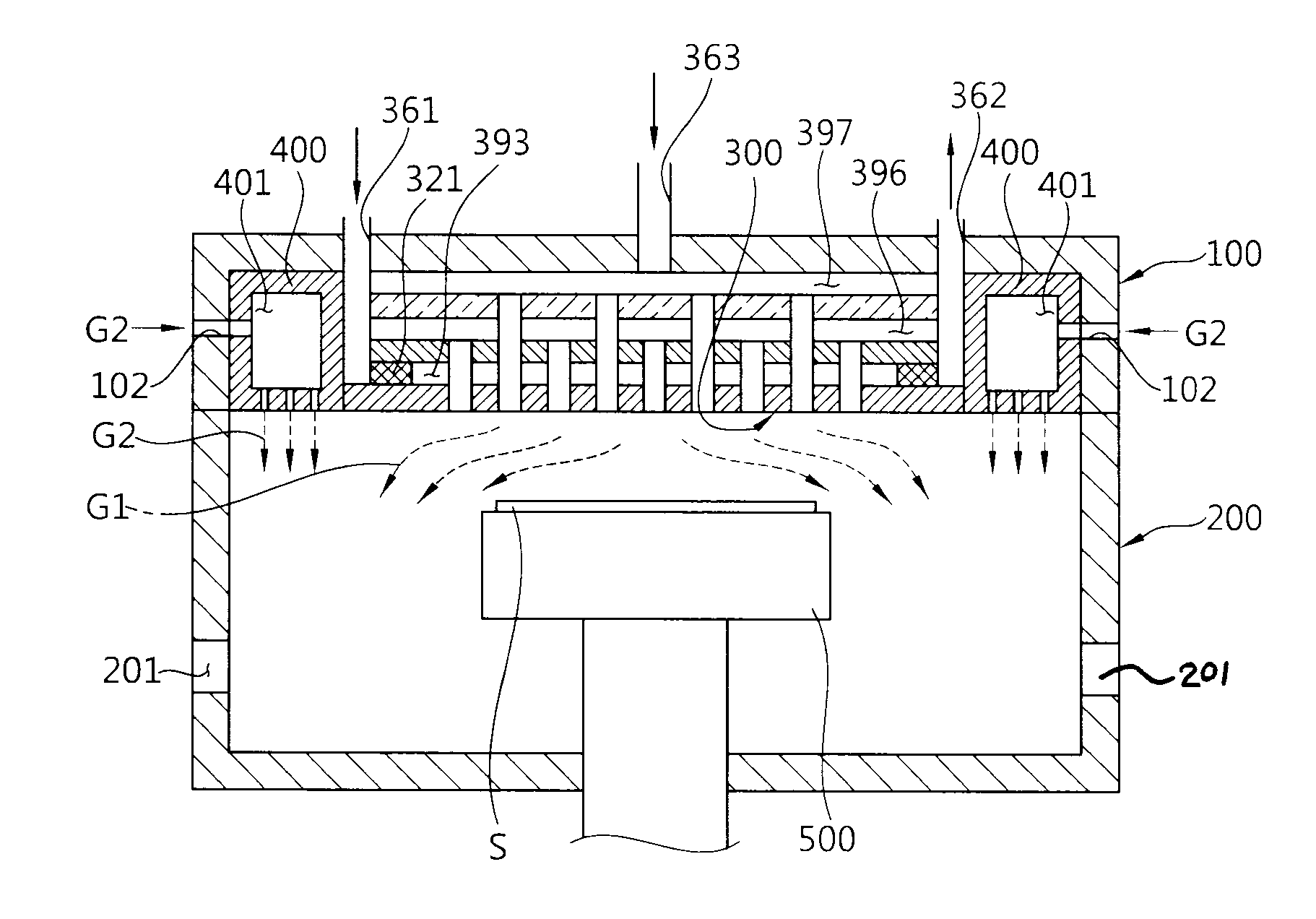
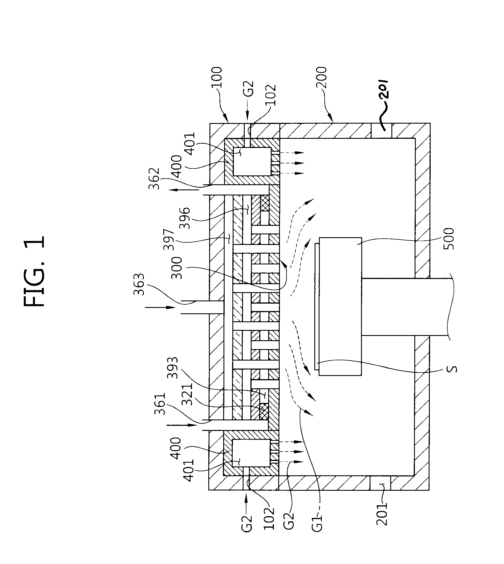
[0018]FIG. 1 is a schematic cross-sectional view of a chemical vapor deposition apparatus according to an embodiment of the present invention. The present embodiment is applicable to other various chemical vapor deposition apparatuses as well as a general metal-organic chemical vapor deposition (MOCVD) apparatus. It should be understood...


PUM

PropertyMeasurementUnit
angleaaaaaaaaaa
angleaaaaaaaaaa
diameteraaaaaaaaaa

Abstract

A gas injection unit allows uniform cooling thereof via smooth flow of coolant and can be easily manufactured. The gas injection unit for a chemical vapor deposition apparatus includes, inter alia: a gas distribution housing; a cooling housing positioned between the gas distribution housing and a processing chamber where a deposition process is performed, and formed with a coolant inlet through which coolant is introduced, and a coolant outlet through which the coolant is discharged; a processing gas pipe of which one end is opened to the gas distribution housing and the other end is opened to the processing chamber, the processing gas pipe penetrating the cooling housing; and a first wall part positioned inside the cooling housing such that an inside of the cooling housing is partitioned into a central path and a peripheral path, and formed with a penetration hole such that the central path communicates with the peripheral path.

Description

CROSS-REFERENCE TO RELATED PATENT APPLICATION[0001]This application claims the benefit of Korean Patent Application No. 10-2009-0068833, filed on Jul. 28, 2009, in the Korean Intellectual Property Office, the disclosure of which is incorporated herein in its entirety by reference.BACKGROUND OF THE INVENTION[0002]1. Field of the Invention[0003]The present invention relates generally to an apparatus for forming a thin layer on a semiconductor substrate, and more particularly to a gas injection unit for a chemical vapor deposition apparatus.[0004]2. Description of the Related Art[0005]A chemical vapor deposition apparatus is a device used for depositing a thin layer on a semiconductor substrate placed on a susceptor inside a processing chamber of the chemical vapor deposition apparatus by injecting a processing gas therein through a gas injection unit. The gas injection unit is an apparatus for uniformly injecting the processing gas toward the substrate positioned inside the processing...

Claims


Application Information

Patent Timeline
Patent Type & Authority Applications(United States)
IPC IPC(8): C23C16/455C23C16/00
CPCC23C16/45565C23C16/45572C23C16/45574H01L21/205
Inventor HAN, MYUNG WOO
Owner LIGADP
Why Eureka
Try Eureka