
Low pressure exhaust gas recirculation apparatus

a technology of exhaust gas recirculation and low pressure, which is applied in the direction of mechanical equipment, machines/engines, and non-fuel substance addition to fuel, etc., can solve the problems of increased size, increased cost, and increased weight, and achieve the effect of increasing the flow quantity and reducing the opening degr

Active Publication Date: 2011-02-03
DENSO CORP
View PDF11 Cites 48 Cited by
  • Summary
  • Abstract
  • Description
  • Claims
  • Application Information

AI Technical Summary

Benefits of technology

[0028]The present invention addresses the above disadvantages. According to the present invention, there is provided a low pressure exhaust gas recirculation apparatus for an internal combustion engine. The internal combustion engine is communicated with an intake air passage, through which intake air is supplied to the internal combustion engine, and an exhaust passage, through which exhaust gas of the internal combustion engine is released to atmosphere. The low pressure exhaust gas recirculation apparatus includes a low pressure exhaust gas recirculation (EGR) flow passage, a low pressure EGR regulating valve, a throttle valve, an electric actuator, a link device, a low pressure EGR opening degree sensor, a low pressure EGR valve return spring, a mechanical stopper and a failure sensing means. The EGR passage is configured to recirculate the exhaust gas as EGR gas from a low exhaust gas pressure area of the exhaust passage to a low negative intake air pressure generating area of the intake air passage. The low pressure EGR regulating valve regulates an opening degree of the low pressure EGR passage to regulate a flow quantity of the EGR gas through the low pressure EGR passage. The throttle valve is adap

Problems solved by technology

Therefore, this will possibly result in the cost increase, the size increase and the weight increase.

Method used


Image

  • Low pressure exhaust gas recirculation apparatus
  • Low pressure exhaust gas recirculation apparatus
  • Low pressure exhaust gas recirculation apparatus

Examples


first embodiment

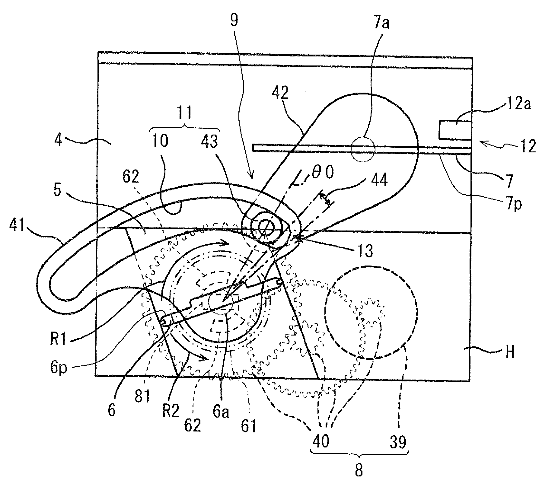
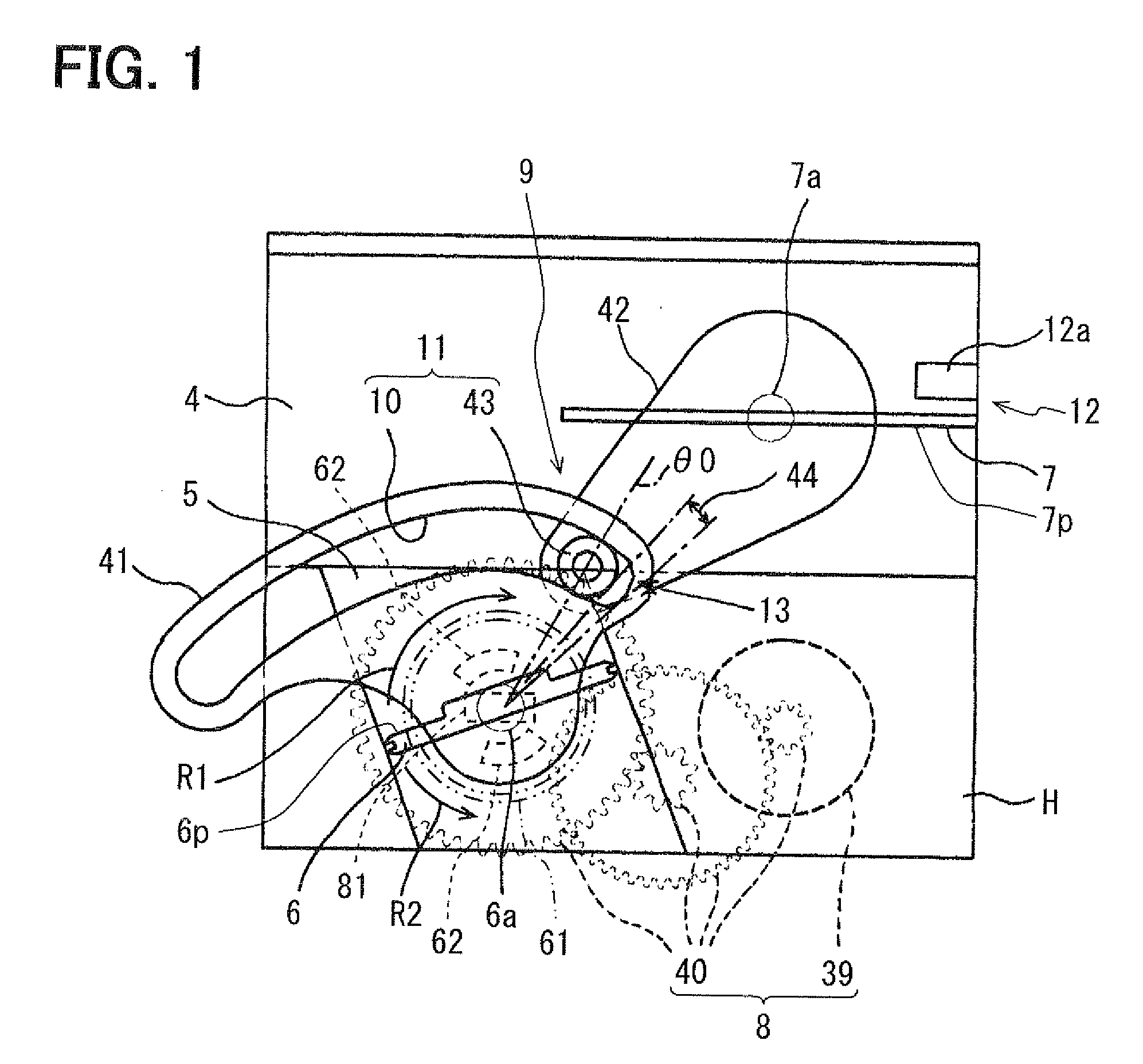
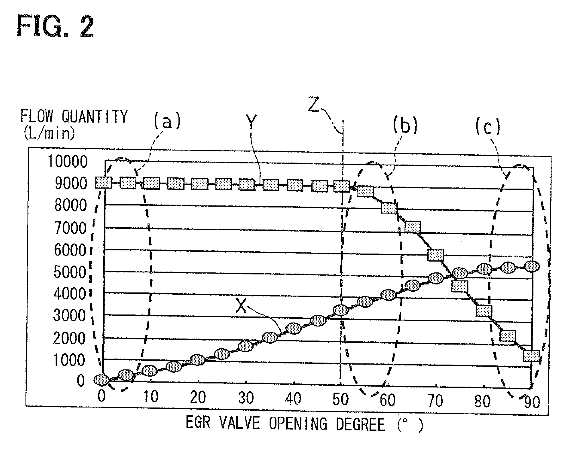
[0041]A low pressure EGR apparatus 1 according to a first embodiment of the present invention will be described with reference to FIGS. 1 to 6. In the present embodiment as well as the subsequent embodiments, similar components will be indicated by the same reference numerals. Also, any one or more of the components of any one of the following embodiments and modifications thereof may be freely combined with any one or more the components of any other one of the following embodiments and the modifications.

[0042]An intake and exhaust system of an internal combustion engine 2 will be described with reference to FIGS. 5 and 6.

[0043]The engine 2 of the present embodiment is a diesel engine for generating a drive force of a vehicle. The engine 2 (more specifically, combustion chambers at cylinders of the engine 2) is communicated with an intake air passage 4 and an exhaust passage 3. The intake air passage 4 conducts intake air to cylinders of the engine 2. The exhaust passage 3 conducts...

second embodiment

[0142]A second embodiment of the present invention will be described with reference to FIG. 7. In the following description of the embodiment, components, which are similar to those of the first embodiment, will be indicated by the same reference numerals. Also, the permanent magnets 62, the magnetic sensor 81 and the low pressure EGR valve return spring 61 of the low pressure EGR apparatus 1 shown in FIG. 1 of the first embodiment are not depicted for the sake of simplicity.

[0143]The low pressure EGR apparatus 1 of the second embodiment has a throttle valve return spring 71, which applies an urging force against the intake air throttle valve 7 toward the opening direction of the intake air throttle valve 7 for opening the intake air passage 4.

[0144]Specifically, the throttle valve return spring 71 of the present embodiment is a helical torsion spring, which is placed at one end part of the throttle valve support shaft 7a and applies the urging force against the throttle valve suppo...

third embodiment

[0146]A third embodiment of the present invention will be described with reference to FIG. 8.

[0147]In the third embodiment, the intake air throttle valve 7 is formed as a butterfly valve, which regulates the opening degree of the intake air passage 4 by rotating the throttle valve support shaft (serving as a rotatable shaft) 7a, which is placed in and fixed to an intermediate part of a valve plate 7p. This butterfly valve is constructed such that a fluid contact surface area of a downstream side valve plate portion 7b of the valve plate 7p, which is placed on the downstream side of the throttle valve support shaft 7a in the intake air flow direction, is larger than a fluid contact surface area of an upstream side valve plate portion 7c of the valve plate 7p, which is placed on the upstream side of the throttle valve support shaft 7a in the intake air flow direction.

[0148]Specifically, as shown in FIG. 8, a length of the downstream side valve plate portion 7b, which is seen from the ...


PUM


Abstract

A low pressure EGR regulating valve is driven by an electric actuator, and an output of the electric actuator is transmitted to an intake air throttle valve through a link device. An ECU executes a failure determination to determine presence of a failure in a case where a sensed opening degree, which is sensed with a low pressure EGR opening degree sensor, is other than an opening degree that corresponds to a maximum opening degree of the throttle valve limited by a mechanical stopper. The ECU executes the failure determination after the energization of the electric actuator is stopped in response to stopping of the engine.

Description

CROSS REFERENCE TO RELATED APPLICATION[0001]This application is based on and incorporates herein by reference Japanese Patent Application No. 2009-179537 filed on Jul. 31, 2009.BACKGROUND OF THE INVENTION[0002]1. Field of the Invention[0003]The present invention relates to a low pressure exhaust gas recirculation (EGR) apparatus.[0004]2. Description of Related Art[0005]A known low pressure EGR apparatus recirculates a portion of exhaust gas of an internal combustion engine from a low exhaust gas pressure area of an exhaust passage (a low exhaust gas pressure generating area, such as an area on a downstream side of a diesel particulate filter, which will be hereinafter abbreviated as DPF) to a low negative intake air pressure generating area of an intake air passage (a low negative intake air pressure generating area, such as an area on an upstream side of a throttle valve).[0006]Previously proposed techniques will be described with reference to FIGS. 10 and 11. In the following desc...

Claims


Application Information

Patent Timeline
IPC IPC(8): F02M25/07F02B47/08
CPCF02M25/0702F02M25/0707F02M25/0709F02M25/0728Y02T10/121F02M25/0786F02M25/0793F02M25/0798F02M25/0731F02M26/05F02M26/06F02M26/25F02M26/28F02M26/49F02M26/51F02M26/64F02M26/70
Inventor MIYAZAKI, SHINSUKEFURUKAWA, AKIRASHIMANE, OSAMUSASAKI, KAZUSHITAKEMOTO, EIJI
Owner DENSO CORP
Learn More