System and method for regenerating heat energy

a heat energy and energy system technology, applied in the field of energy systems, can solve the problems of insufficient efficiency of the energy system, and achieve the effect of enhancing method efficiency

Inactive Publication Date: 2011-02-03
EXENCOTECH
View PDF7 Cites 11 Cited by
  • Summary
  • Abstract
  • Description
  • Claims
  • Application Information

AI Technical Summary

Benefits of technology

[0024]A main advantage with the method for regenerating heat energy according to the present invention is that the method efficiency is enhanced in relation to the efficiency of known methods.
[0025]A

Problems solved by technology

A problem and a disadvantage with the solutions disclosed in the above mentioned documents in particular, and in many known energy syste

Method used


Image

  • System and method for regenerating heat energy
  • System and method for regenerating heat energy
  • System and method for regenerating heat energy

Examples


first embodiment

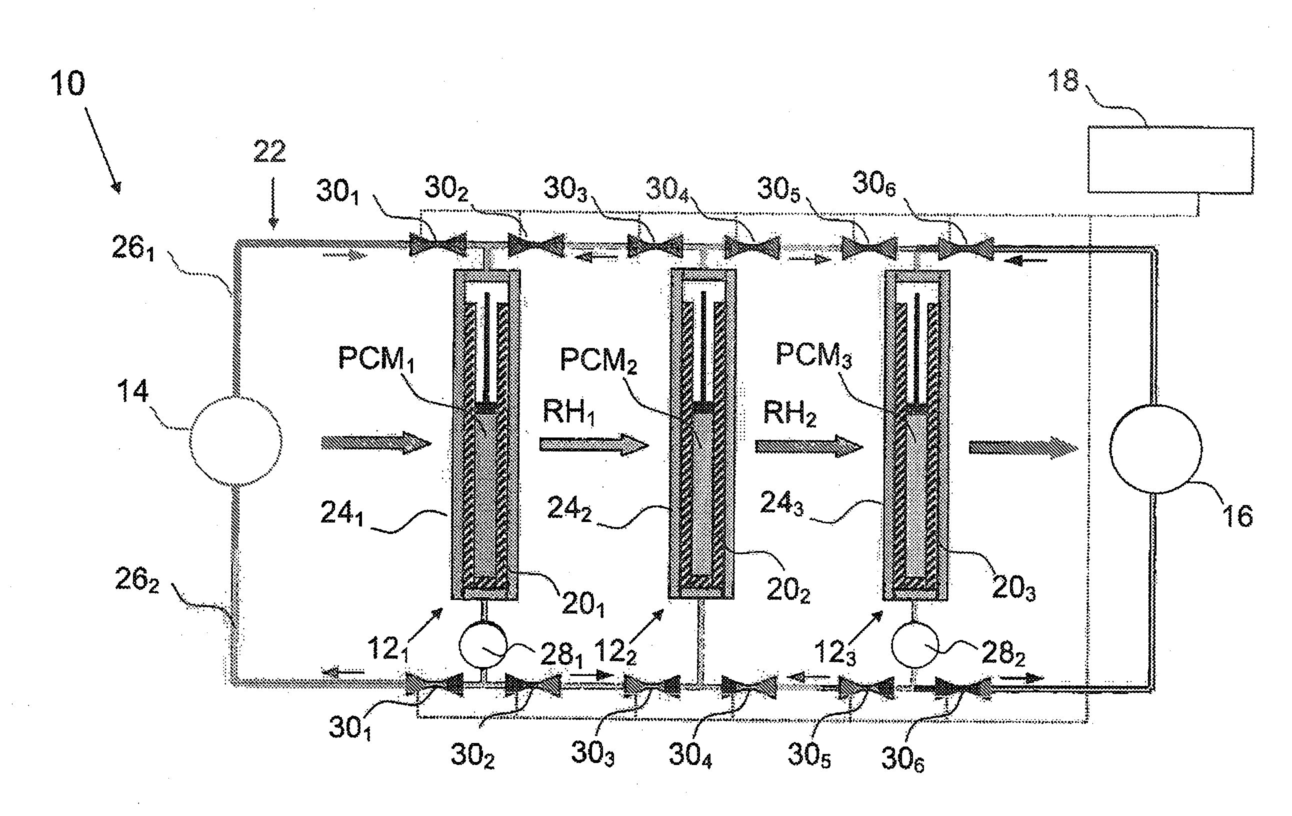
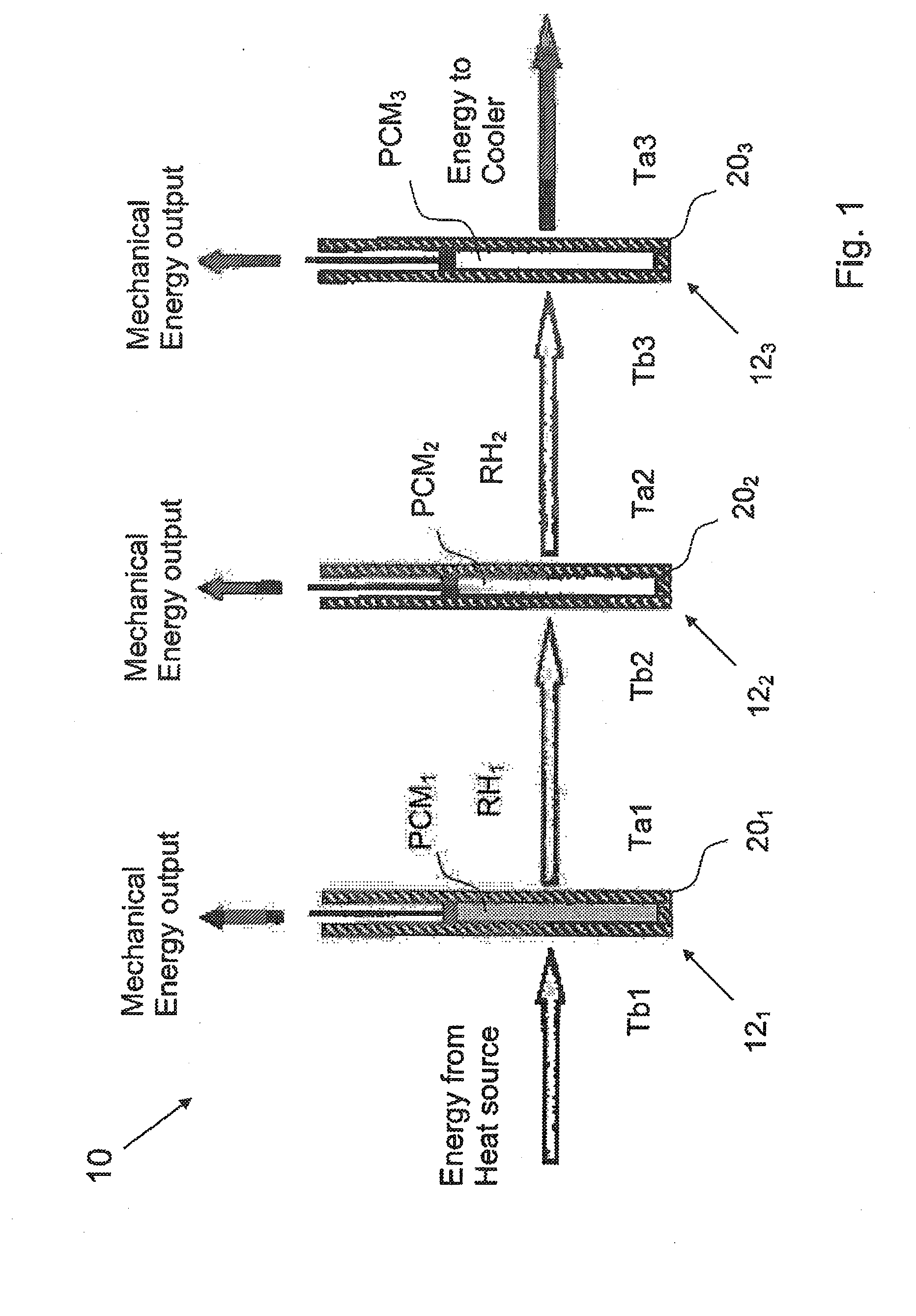
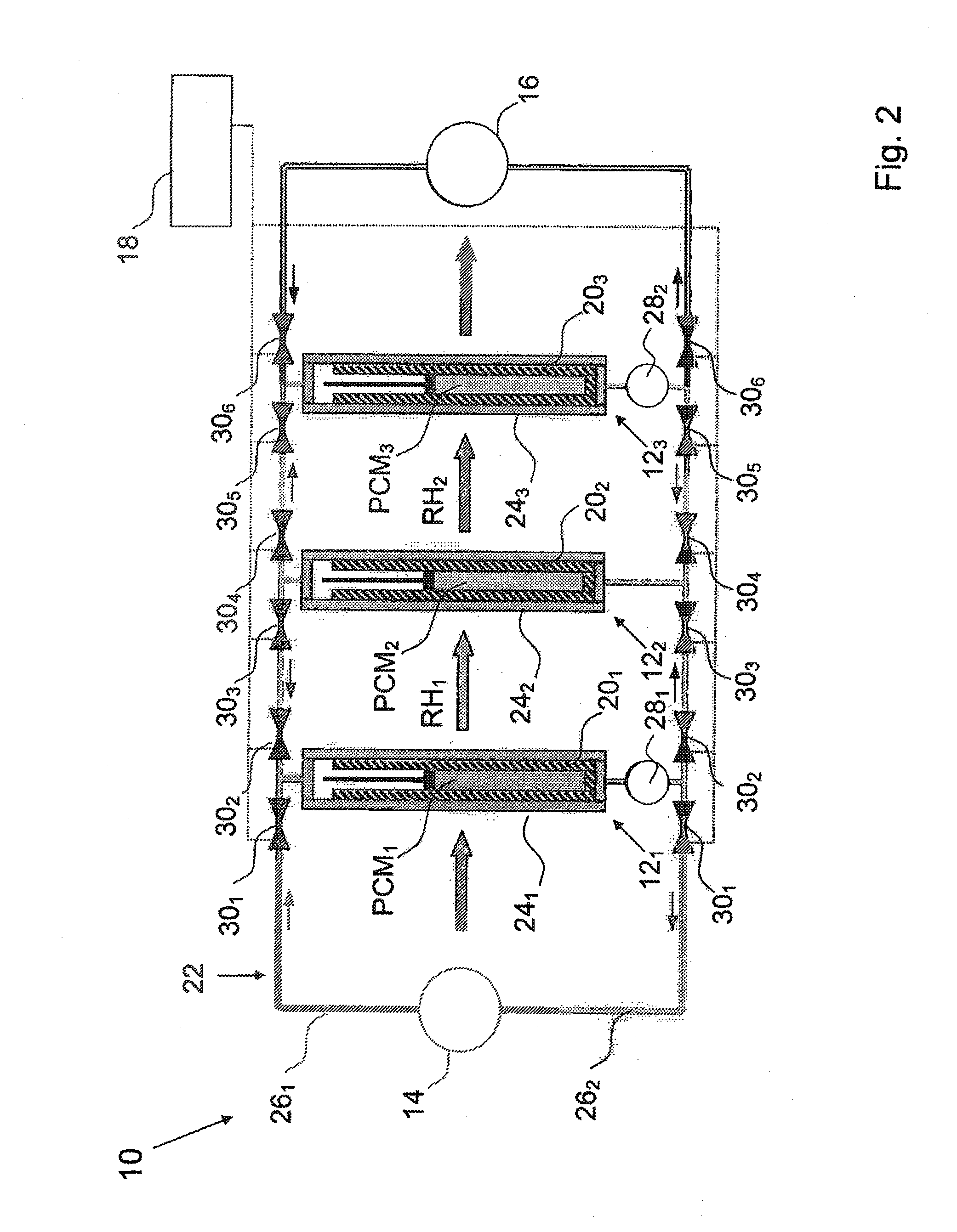
[0045]In FIG. 1 there is disclosed a schematic diagram of an energy system 10 according to the present invention. The energy system 10 is operable to regenerate heat energy. In FIG. 1, the energy system 10 comprises three energy cells 121-123, which are connected in a sequence. Each energy cell 121;122;123 comprises a chamber means 201;202;203, which in turn comprises a phase change material PCM1;PCM2;PCM3.

[0046]Each phase change material PCM1;PCM2;PCM3 has an average phase change temperature PCMT1;PCMT2;PCMT3, wherein PCMT1>PCMT2>PCMT3. The average phase change temperature of the first phase change material PCM1 is defined as PCMT1=(Ta1+Tb1) / 2, wherein the phase change occurs between the two temperatures Ta1 and Tb1. The same applies for the other energy cells 122 and 123 with the corresponding phase change materials PCM2 and PCM3. Each energy cell 121;122;123 either produces mechanical energy, schematically disclosed in FIG. 1 with vertical arrows, and rest heat energy RH1;RH2;RH3...

second embodiment

[0055]In FIG. 3 there is disclosed a schematic diagram of an energy system 10 according to the present invention. In this embodiment there are two groups of energy cells, a first group with four energy cells 121, and a second group with four energy cells 122. In this embodiment, there are two pump means 281 and 282, and four valve means 301, 302.

third embodiment

[0056]In FIG. 4 there is disclosed a schematic diagram of an energy system 10 according to the present invention. In this embodiment there are three groups of energy cells, a first group with four energy cells 121, a second group with four energy cells 122, and a third group with four energy cells 123. In this embodiment, there are two pump means 281 and 282, and six valve means 301-303.


PUM


Abstract

The present invention relates to a method for regenerating heat energy with the aid of an energy system comprising n number of energy cells (121, . . . ,12n), wherein n is an integer, and n>2. The energy cells (121, . . . ,12n) are connected in sequence. Each energy cell (121, . . . ,12n) comprises a phase change material (PCM1, . . . ,PCMn), wherein PCMT1>PCMT2>, . . . , >PCMTn. The energy cells (121, . . . ,12n) performs the steps:
    • to produce mechanical energy, which also causes rest heat energy (RH1, . . . ,RHn) stored in said energy cell (121, . . . ,12n) when the phase change material (PCM1, . . . ,PCMn) changes from solid phase to liquid phase; or
    • to cool down when the phase change material (PCM1, . . . ,PCMn) changes from liquid phase to solid phase;
    • to transfer said rest heat energy (RHx) from one energy cell (12x) which is cooling down as input energy to the next energy cell (12x+1), said method comprises the step:
    • with the aid of a control means connected to said energy cells (121, . . . ,12n), to control said system alternately between a first phase, and a second phase, wherein, during said first phase, every two energy cells (121, 123, 125, . . . ) produces mechanical energy, and every two energy cells (122, 124, 126, . . . ) are cooling down, and vice versa during said second phase.

Description

FIELD OF THE INVENTION[0001]The present invention relates, in a first aspect, to an energy system operable to regenerate heat energy.[0002]According to a second aspect, the present invention relates to a method for regenerating heat energy.BACKGROUND OF THE INVENTION[0003]to The patent document DE 10 2005 039 270 A1 relates to a device and method for numerous converting of heat energy into mechanical energy, storing the mechanical energy and converting the stored energy to electrical energy. Expanded through applied heat, expanding bodies (EB) (12) are interconnected as desired in a cascade or in parallel. Lengthening produced through heat and shortening produced by cooling is made usable at the end of the EB in the form of energy. A device heats up the EB. Linked to EB output, a cylinder piston system reduces overall strokes. A mixing / heat exchanger device optimizes use of heat. An independent claim is also included for method for operating a system for producing energy by attainin...

Claims


Application Information

Patent Timeline
IPC IPC(8): F28D19/00F28D15/04
CPCF03G7/06
Inventor OSTLUND, BENGT
Owner EXENCOTECH
Why Eureka
Try Eureka