Suspension system for vehicle

a suspension system and vehicle technology, applied in the direction of shock absorbers, mechanical devices, transportation and packaging, etc., can solve the problems of deteriorating the riding comfort of the vehicle, interfering with the steering stability of the vehicle, etc., to reduce the adverse effect, reduce the distance between the floating unit, and reduce the adverse effect

Active Publication Date: 2011-02-03
TOYOTA JIDOSHA KK +1
View PDF12 Cites 38 Cited by
  • Summary
  • Abstract
  • Description
  • Claims
  • Application Information

AI Technical Summary

Benefits of technology

[0064]The above two forms (17) and (18) are for decreasing the adverse effect due to the provision of the relative-displacement limiting mechanism. The former form includes an arrangement in which, when the floating unit moves near to one end of the movable range, the actuator force to be generated in the relative-vibration damping control is made large, whereby a relatively large resistance force is given to the movement of the floating unit toward one end of the movable range, for instance. According to the arrangement, the floating unit is prevented from reaching one end or the above-indicated impact generated upon reaching can be made small. The latter form may be arranged such that the actuator force to be generated in the relative-vibration damping control is increased as the floating unit moves closer to one end of the movable range, namely, the actuator force is increased with a decrease in the distance between the floating unit and one end of the movable range. According to the arrangement, the floating unit is prevented from reaching one end or the above-indicated impact generated upon reaching can be made small, as in the former form.

Problems solved by technology

The vibration may deteriorate the riding comfort of the vehicle and interfere with the steering stability of the vehicle, for instance.

Method used


Image

  • Suspension system for vehicle
  • Suspension system for vehicle
  • Suspension system for vehicle

Examples


first embodiment

1. First Embodiment

(A) Structure of Suspension System

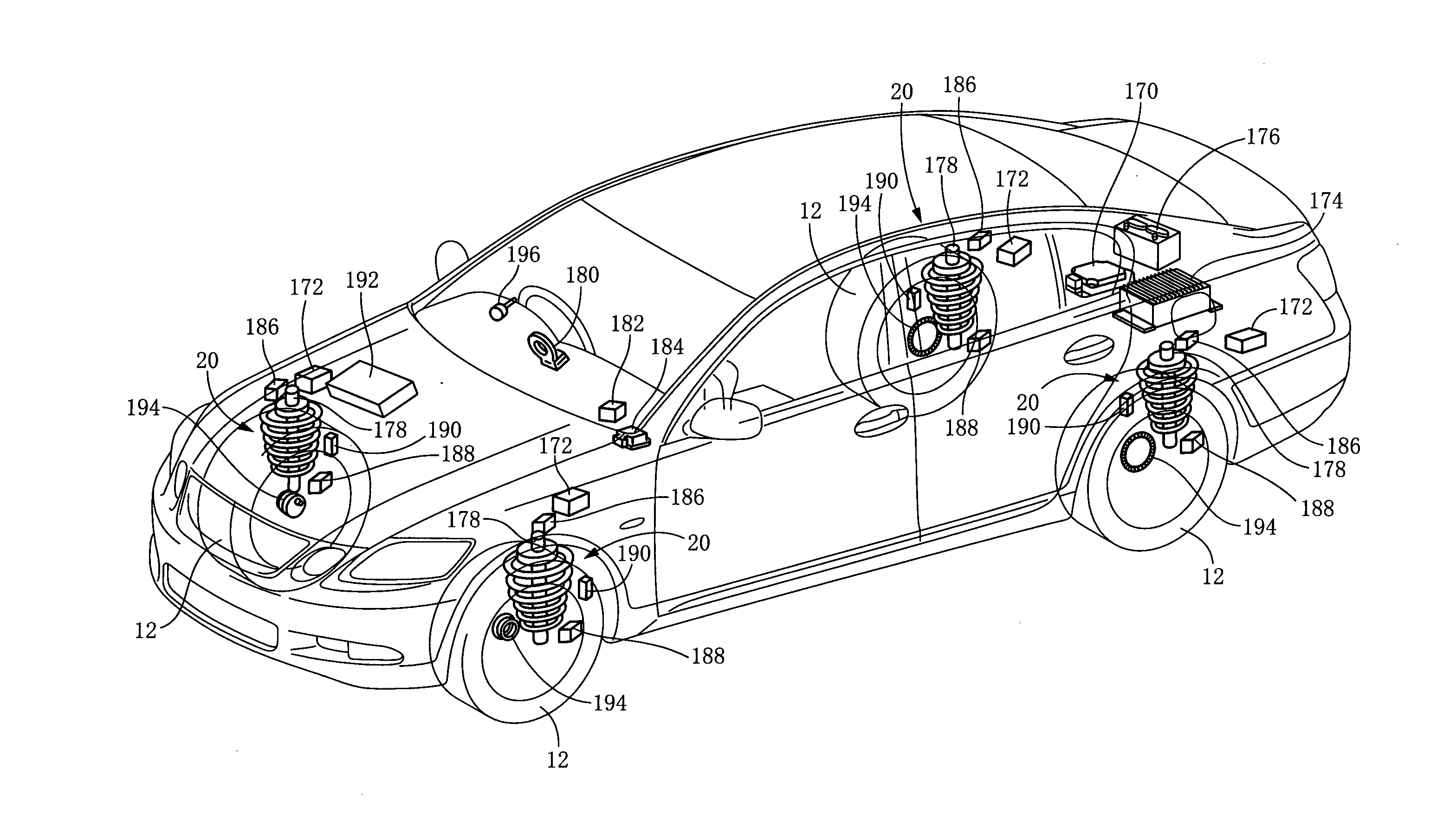
[0086]As shown in FIG. 1, a suspension system for a vehicle according to a first embodiment includes four suspension apparatuses 20 provided so as to correspond to respective four wheels 12, i.e., a front left wheel, a front right wheel, a rear left wheel, and a rear right wheel, and a control system that governs a control of the suspension apparatuses 20. Two of the four suspension apparatuses 20 for the respective two front wheels that can be steered are substantially identical in construction with another two of the four suspension apparatuses 20 for the respective two rear wheels that cannot be steered, except for a mechanism that enables the wheels to be steered. Accordingly, the structure of the suspension apparatuses 20 will be explained focusing on one of the two suspension apparatuses 20 for the rear wheels.

i) Structure of Suspension Apparatus

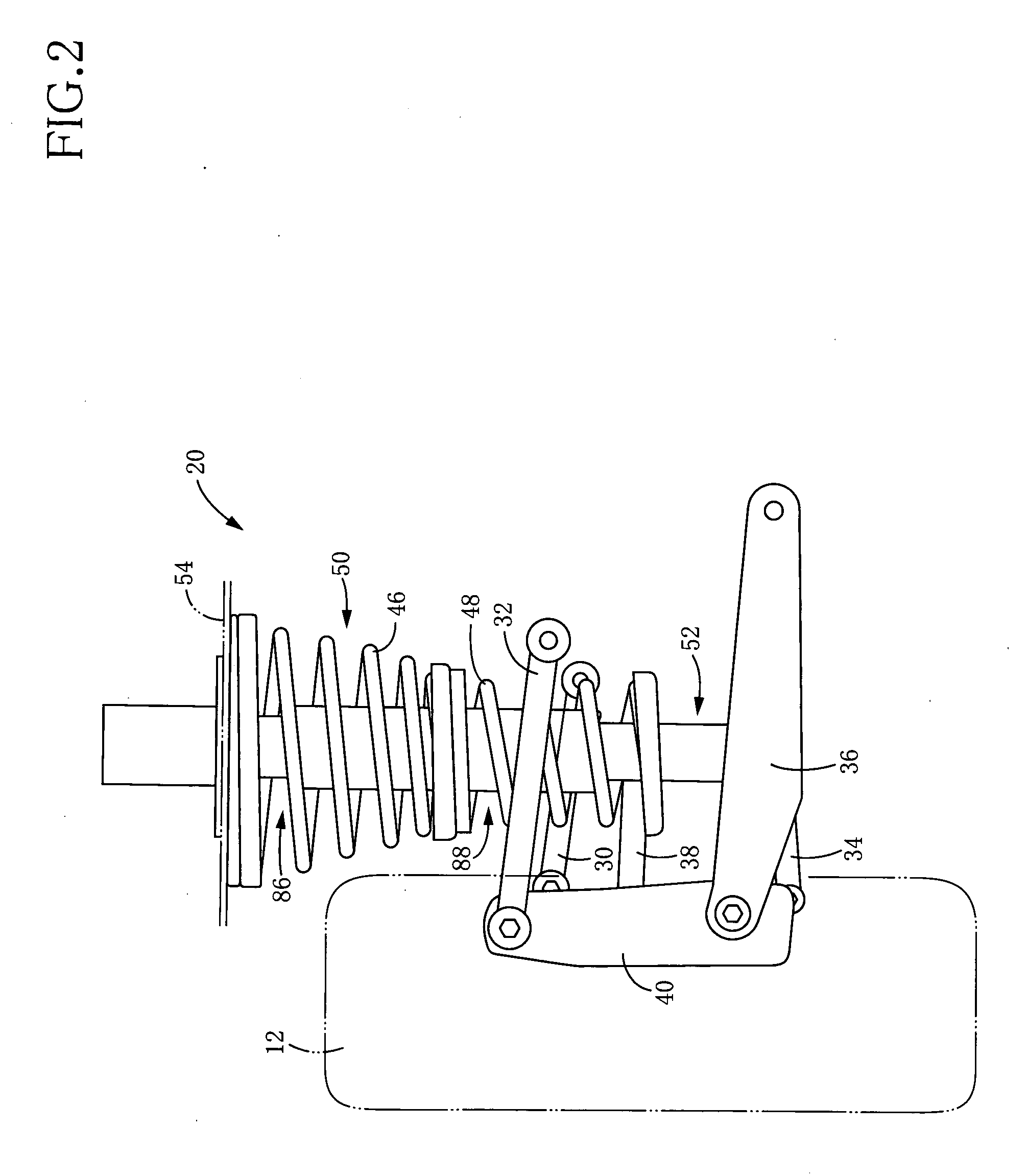
[0087]As shown in FIG. 2, each suspension apparatus 20 is of an independent type...

second embodiment

2. Second Embodiment

(A) Structure of Suspension System

i) Overall Structure

[0149]Like the suspension system according to the illustrated first embodiment, a suspension system for a vehicle according to a second embodiment has four suspension apparatuses. However, each suspension apparatus in the second embodiment differs in structure from the suspension apparatuses 20 according to the first embodiment.

[0150]More specifically, in each suspension apparatus according to the second embodiment, a spring·actuator Assy 250 shown in FIG. 15 is employed in place of the two compression coil springs 46, 48, the actuator 50, the damper 52, and the connecting mechanism 64 employed in the suspension system of the first embodiment. In the spring·actuator Assy 250, a main spring which elastically connects the sprung portion and the unsprung portion, namely, a suspension spring, and an electromagnetic actuator are united. In this respect, the main spring is an air spring as one sort of a fluid spring...


PUM


Abstract

A suspension system for a vehicle, including: an electromagnetic actuator configured to generate an actuator force and including a sprung-side unit supported by a sprung portion, an unsprung-side unit supported by an unsprung portion, a screw mechanism, and an electromagnetic motor; a connecting mechanism including a support spring for permitting one of the sprung-side and unsprung-side units to be floatingly supported as a floating unit by a unit-floatingly support portion that is one of the sprung and unsprung portions by which the floating unit is supported; and a controller including a sprung-vibration-damping control portion and a relative-vibration-damping control portion that is configured to execute a relative-vibration damping control for damping a vibration of the floating unit caused by the structure in which the floating unit is floatingly supported by the support spring.

Description

TECHNICAL FIELD[0001]The present invention relates in general to a suspension system mounted on a vehicle, and more particularly to a suspension system for a vehicle including an electromagnetic actuator for vibration damping.BACKGROUND ART[0002]As a suspension system including an electromagnetic actuator functioning as a shock absorber, namely, as the so-called electromagnetic suspension system, there is known one described in the following Patent Document 1, for instance. The electromagnetic suspension system has an advantage that a vibration of a sprung portion can be effectively damped based on a skyhook damper theory, and has been actively developed in the field of vehicles. At present, various proposals with regard to the control of the actuator have been made. In an electromagnetic suspension system described in the following Patent Document 2, there has been developed a control for compensating for an internal inertial force of the actuator.[0003]Patent Document 1 WO 02 / 0800...

Claims


Application Information

Patent Timeline
Patent Type & Authority Applications(United States)
IPC IPC(8): B60G17/0165
CPCB60G17/0157B60G17/06B60G2400/252B60G2400/102B60G2400/206B60G2202/42
Inventor INOUE, HIROFUMIKONDO, TAKUHIRO
Owner TOYOTA JIDOSHA KK
Why Eureka
Try Eureka