Magnetic sensor

a technology of magnetic sensor and sensor, applied in the field of magnetic sensor, can solve the problems of improving stability and far from a performance level that is sufficiently stable, and achieve the effect of reducing the resistance of the top electrode and the bottom electrode, detecting the signal magnetic field further accurately, and reducing the variation in behavior

Active Publication Date: 2011-02-03
TDK CORPARATION
View PDF6 Cites 41 Cited by
  • Summary
  • Abstract
  • Description
  • Claims
  • Application Information

AI Technical Summary

Benefits of technology

[0013]Advantageously, the stem section of the top electrode, having the branch section which is connected with one of the magnetoresistive films, is connected to the stem section of the bottom electrode, having the branch section which is connected with another one of the magnetoresistive films adjacent thereto along the series alignment direction. This allows all of the directions of the read-out currents flowing in the respective magnetoresistive films to be aligned in the same direction, making it possible to reduce a variation in behavior in each of the magnetoresistive films in response to the signal magnetic field, and to detect the signal magnetic field further accurately.
[0014]Advantageously, the extending direction of the branch section of each of the top electrodes and the extending direction of the branch section of each of the bottom electrodes correspond to a direction orthogonal to the series alignment direction of the magnetoresistive films. This allows a length of the branch section to be the shortest while separating the magnetoresistive film away from the stem section, making it possible to effectively reduce a resistance of the top electrode and the bottom electrode. Also, this allows the branch section of the top electrode and the branch section of the bottom electrode to extend in parallel to each other, making it possible to sufficiently reduce an influence of electromotive force generated by the current flowing in both branch sections.
[0015]Advantageously, the branch sections of the top electrodes and the branch sections of the bottom electrodes each have cross-sectional area equal to one another. The cross-sectional area represents an area of a cross-section orthogonal to the direction in which the branch section extends. This makes it possible to sufficiently cancel the induction magnetic field generated around each of the branch sections.
[0016]Advantageously,...

Problems solved by technology

However, with further reduction in size, even a magnetic sensor utilizing a GMR element or a MTJ element is more likely to be susceptible to an external noise such as an unnecessary magnetic field, presenting a problem of improvement in stability in terms of a detectio...

Method used


Image

  • Magnetic sensor
  • Magnetic sensor
  • Magnetic sensor

Examples


first embodiment

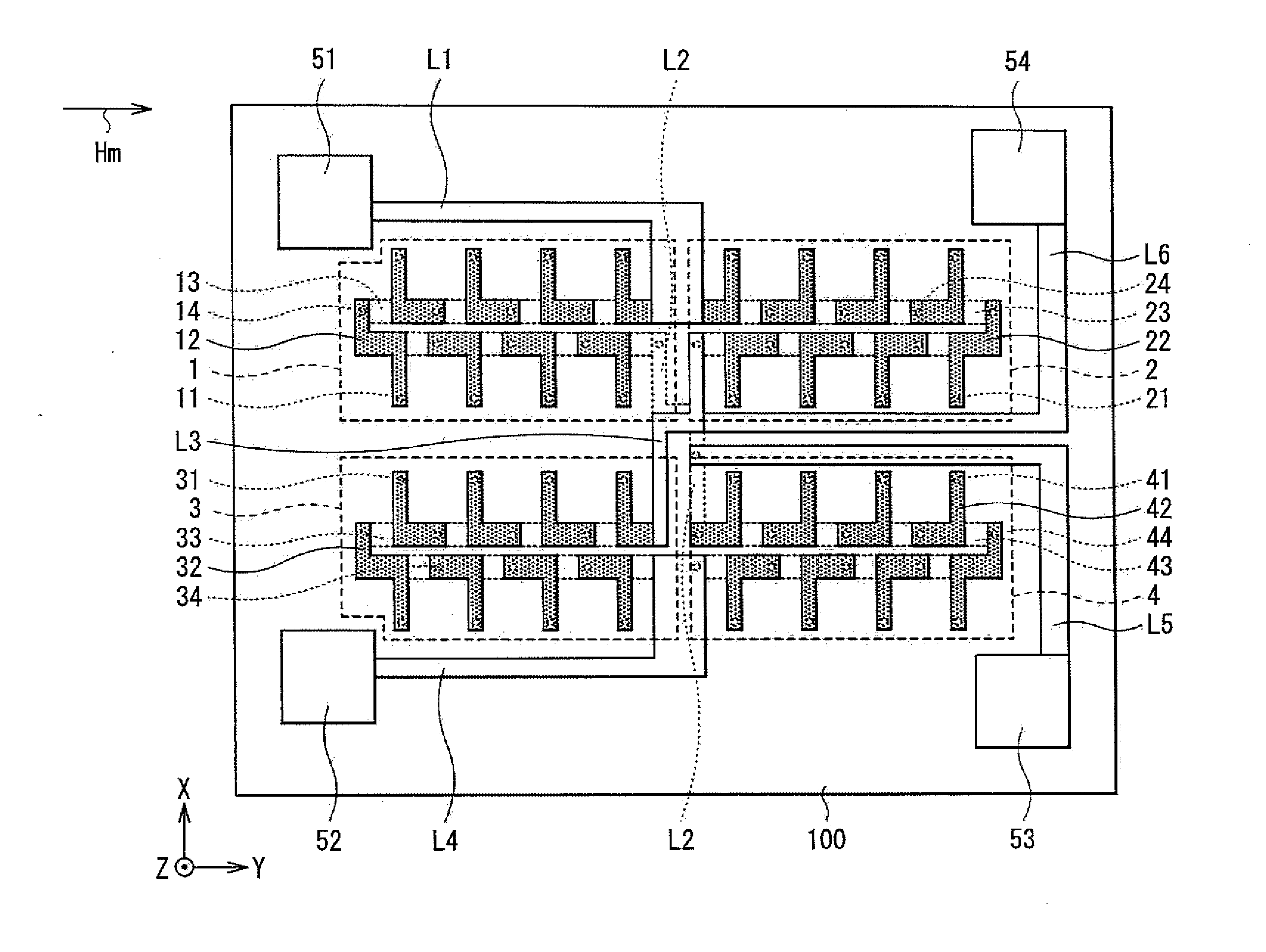
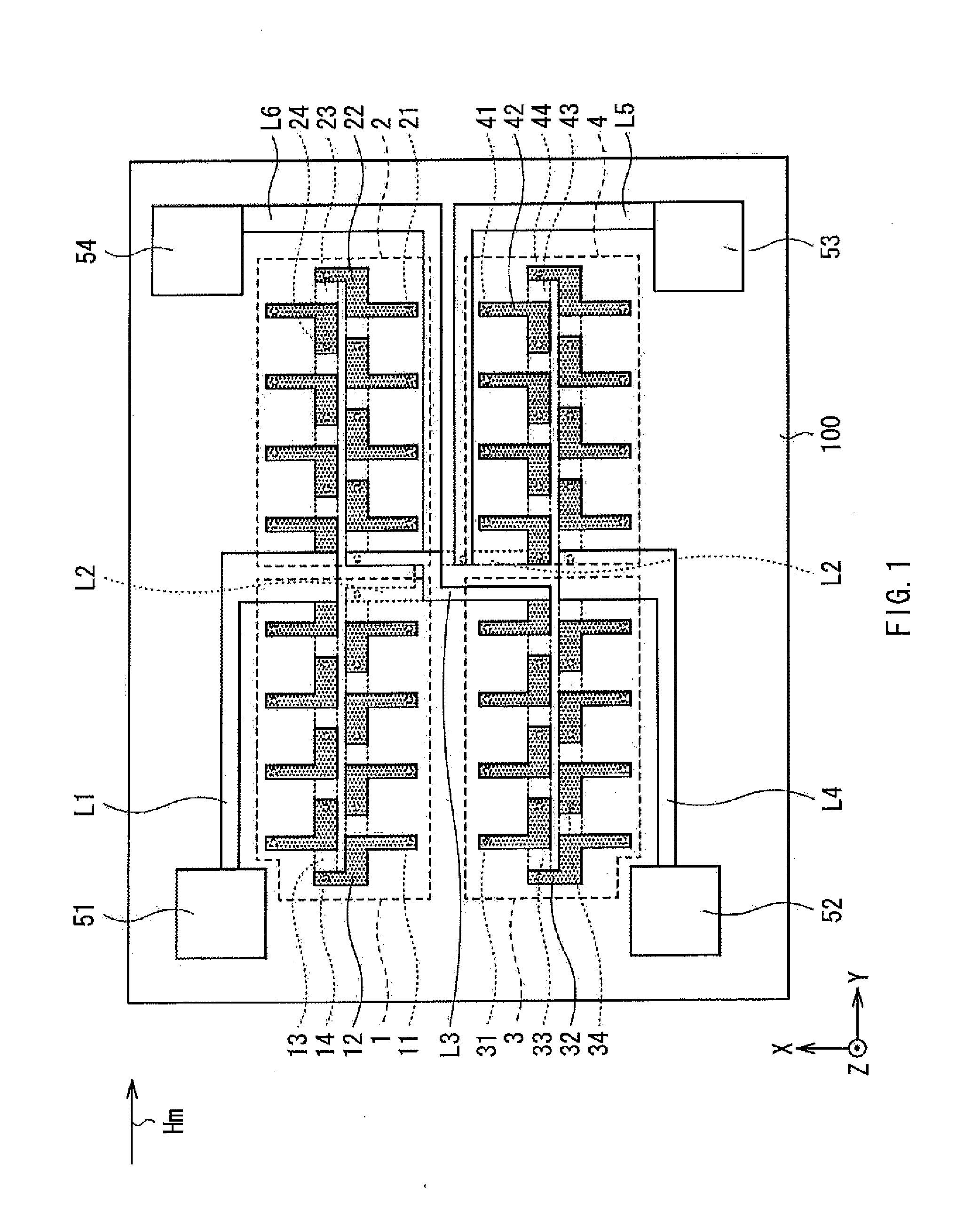
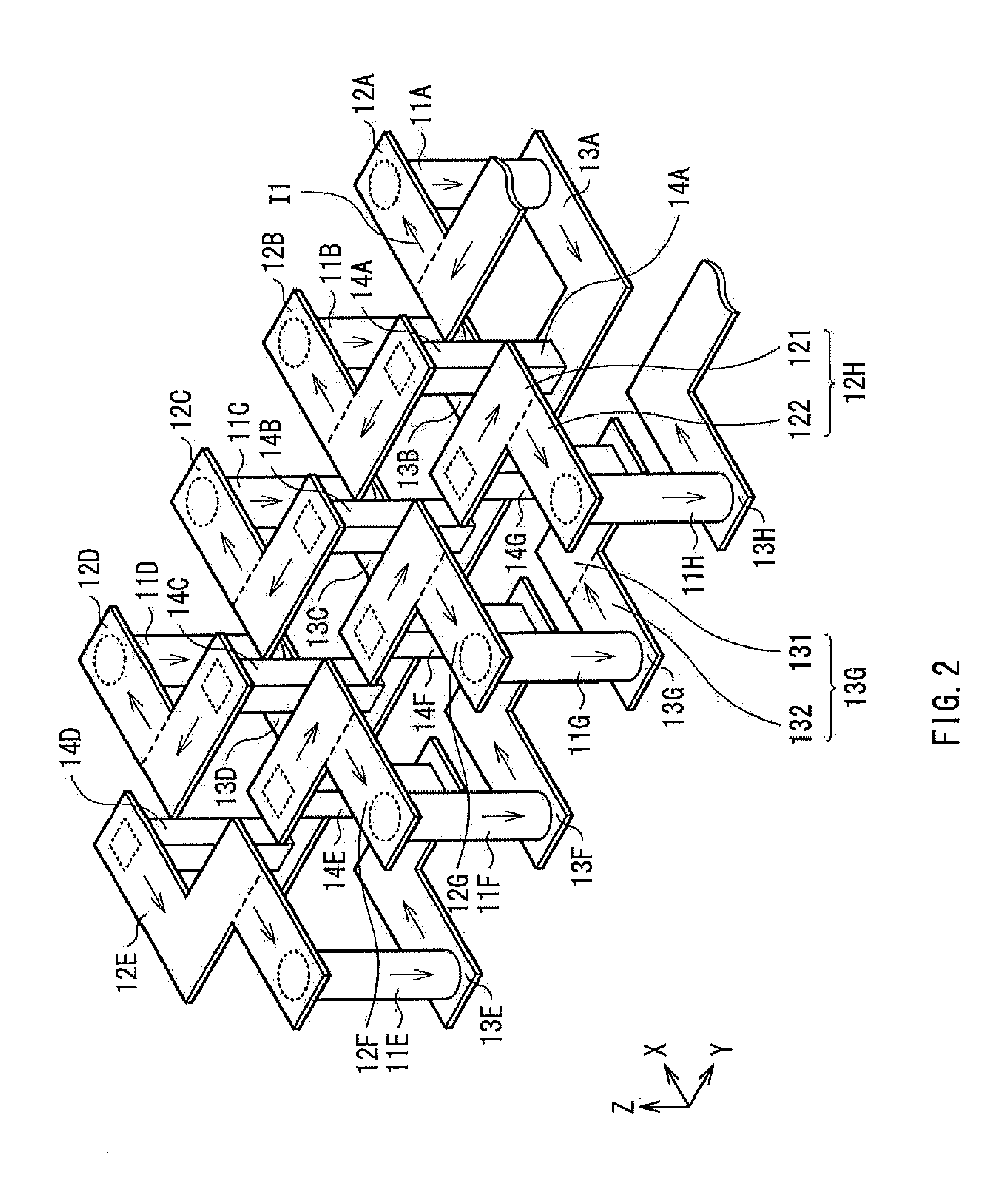
[0040]First, a configuration of a magnetic sensor according to a first embodiment of the invention will be described with reference to FIGS. 1 to 16B. FIG. 1 is a plan view illustrating an overall configuration of the magnetic sensor according to the first embodiment. FIG. 2 is an enlarged perspective view illustrating a main configuration of the magnetic sensor.

[0041]The magnetic sensor according to this embodiment includes first to fourth magnetoresistive (MR: Magneto-Resistive effect) elements 1 to 4 (hereinafter may be simply referred to as “MR elements”), pads 51 to 54, interconnections L1 to L6, and a difference detector AMP (which will be described later), and so forth, which are provided on a substrate 100. The magnetic sensor detects a direction and a magnitude of a signal magnetic field Hm which changes in a certain plane of rotation (in an XY plane in this embodiment). For example, the pad 51 is connected to a power source Vcc which will be described later, and the pad 52...

first modification

[First Modification]

[0078]Hereinafter, a first modification of the magnetic sensor according to the first embodiment will be described. In the first embodiment described above, all of the magnetization fixed layers 63 of the stacked bodies 11, 21, 31, and 41 in the first MR elements 1 to 4 have the synthetic structure. However, in the first modification, the magnetization fixed layers 63 in the first and the third MR elements 1 and 3 each may be configured by a single ferromagnetic material layer or by a plurality of ferromagnetic material layers, instead of the synthetic structure. On the other hand, the second and the fourth MR elements 2 and 4 each have the synthetic structure similar to that of the embodiment described above. That is, the total magnetic moment MOP of the pinned layer 633 is made larger than the total magnetic moment MIP of the pinned layer 631.

[0079]As in the embodiment described above, this modification also makes it possible to allow the orientation of the mag...

second embodiment

[0080]Now, a configuration of a magnetic sensor according to a second embodiment of the invention will be described with reference to figures including FIG. 17. FIG. 17 schematically illustrates a configuration of a magnetic field detecting circuit in the magnetic sensor according to the second embodiment. The magnetic sensor of this embodiment has a configuration similar to that of the first embodiment described above, except that the first MR element 1 is replaced by a second constant current source CG2, and that the second MR element 2 is replaced by a first constant current source CG1. Note that the same or equivalent elements as those of the first embodiment described above are denoted with the same reference numerals, and will not be described in detail.

[0081]Referring to FIG. 17, the first constant current source CG1 and the second constant current source CG2 supply the third MR element 3 and the fourth MR element 4 with a constant current I1 and a constant current I2, having...


PUM


Abstract

A magnetoresistive element includes magnetoresistive films each having an upper surface and a lower surface, and conductors combining the magnetoresistive films in series and including top electrodes and bottom electrodes. Each one of the top electrodes and corresponding one of the bottom electrodes oppose each other to sandwich corresponding one of the magnetoresistive films. Each electrode of the top electrodes and the bottom electrodes includes a stem section and a branch section, the stem section extending in a direction along a series alignment direction of the magnetoresistive films, and the branch section extending along the lamination plane in a direction intersecting a direction in which the stem section extends. The branch section in the top electrode is in contact with an upper surface of the corresponding magnetoresistive film, and the branch section in the bottom electrode is in contact with a lower surface of the corresponding magnetoresistive film.

Description

BACKGROUND OF THE INVENTION[0001]1. Field of the Invention[0002]The invention relates to a magnetic sensor capable of detecting a change in a magnetic field highly sensitively.[0003]2. Description of the Related Art[0004]In general, when detecting a minute control current flowing in a circuit of a control device accurately, a method is used, where resistors are connected in series in the circuit and a voltage drop of the resistors is measured. However, this may cause some adverse effect on a control system, since a load different from that of the control system is applied. Thus, a method which performs indirect measurement by detecting a gradient of a current magnetic field generated by a control current has been used. For example, the indirect measurement method is achieved by winding a measurement line around a toroidal core, and supplying a control current to the measurement line, to detect a magnetic flux generated in a central part of the toroidal core with a Hall element.[0005...

Claims


Application Information

Patent Timeline
IPC IPC(8): G01R33/02H01L43/00
CPCG01R33/091H01L43/08G01R33/098H10B61/00H10N59/00
Inventor OHTA, NAOKISAKAI, MASANORIHIRABAYASHI, HIRAKU
Owner TDK CORPARATION
Why Eureka
Try Eureka