[0007]A particularly effective cooling arrangement which is favourable for the applied components, is achieved by way of this design according to the invention. Thereby, a longitudinal flow between the motor and the lower side of the housing of the frequency converter is formed along the longitudinal ribs, thus where the housing is arranged close to the motor, and this flow ensures an intensive cooling of the components of the power circuit, which are connected in this region on the inside to the base. This cooling flow is produced by the fan of the motor, on which the frequency converter is arranged. Moreover however, a
convection cooling flow forms on account of the cooling ribs which are arranged in an external region transversely or obliquely to the longitudinal ribs, and this
convection cooling flow, although having a lower flow speed than the longitudinal cooling
airflow, given a suitable design of the transverse ribs or oblique ribs, is however sufficient to cool the components of the input circuit and / or intermediate circuit of the frequency converter, these components producing heat and according to the invention, being connected with a non-positive fit and in a heat-conducting manner to the housing in this region, on the inside. The arrangement is moreover such that in operation, in the outer region, a lower temperature level sets in than in the middle region, where the
power electronics are arranged. It is therefore possible by way of the design according to the invention, to arrange the electronic components of the power circuit in the direct vicinity of the electrical / electronic components of the input circuit and / or intermediate circuit, without thermally overloading these.
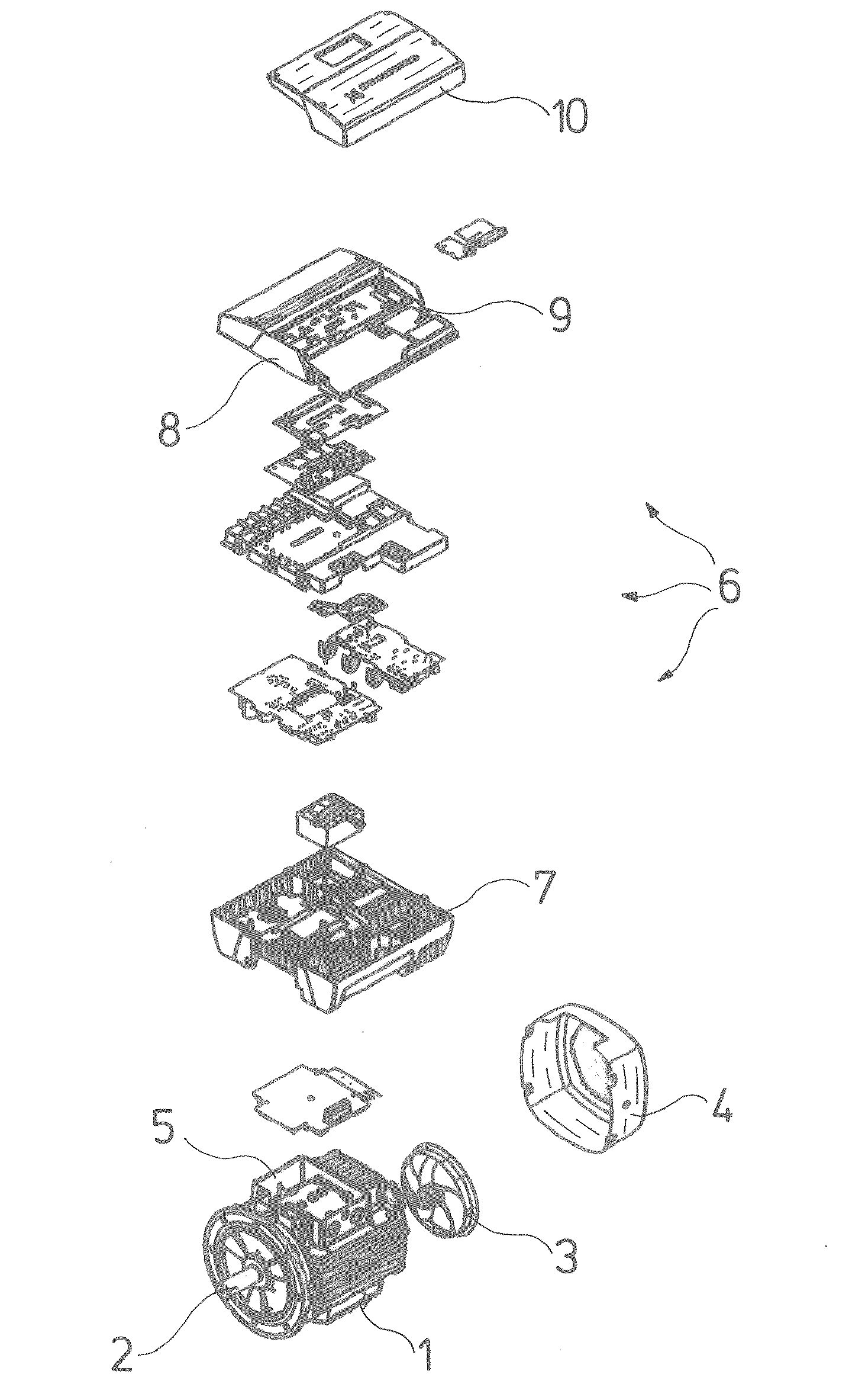
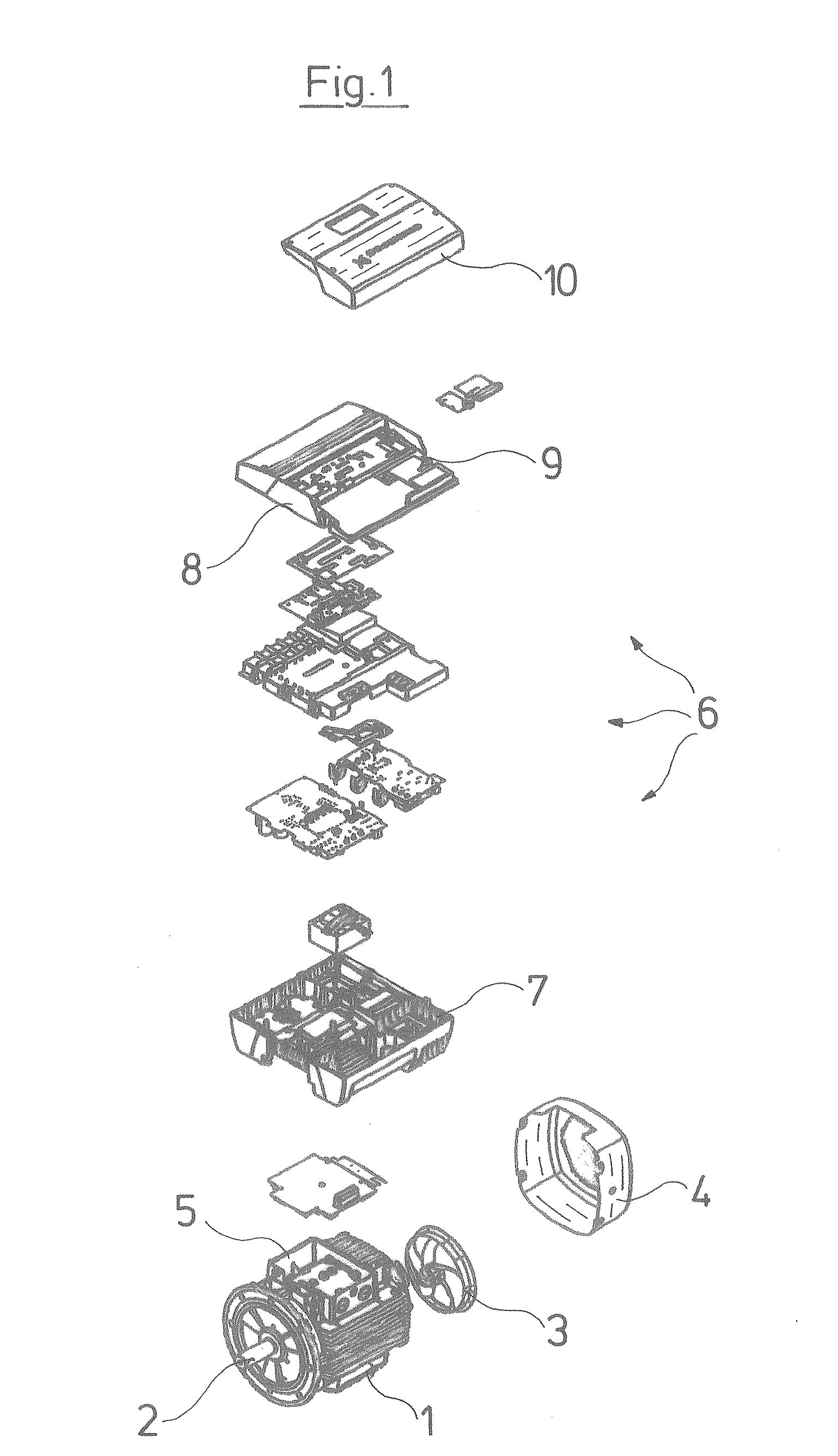
[0008]According to a further formation of the invention, the outer contour of the frequency converter housing is curved on the lower side, corresponding to the outer contour of the electric motor. The outer contour of the electric motor may be curved by way of this. A
free space which otherwise may not be used, may be utilized for the frequency converter way of this. A further
advantage of this curved outer contour of the frequency converter on its lower side, i.e. its side facing the motor, is that apart from the middle region in which the
power electronics are arranged, the outer regions of the housing base which are arranged next to this, lie deeper, which encourages the maintenance of a different thermal level within the frequency converter, in particular prevents the high temperatures prevailing in the power circuit from arising in these outer regions of the frequency converter housing. Moreover, space for bulky components such as coils and capacitors may be provided in the outer regions by way of this design of the housing.
[0011]A good thermally conductive contact to the heat-producing components is created via these connection surfaces. Thereby, according to a further formation of the invention, it is particularly advantageous if the heat connection surfaces in the outer region or in the two outer regions are arranged at a different, in particular deeper level than in the middle region. By way of this, one the one hand a good spatial utilization of the inner space is achieved, and on the other hand the previously described different temperature levels within the frequency converter housing are encouraged.
[0015]With the previously described
topography of the frequency converter housing, and the arrangement of the components, these heat-producing components may be advantageously arranged on a circuit board which is arranged at a distance to the housing base in a manner such that the heat-producing components in each case have a heat connection surface facing the housing base, and are connected with a non-positive fit and thus in a highly heat-conducting manner to the associated heat connection surface by way of a
coupling body. This arrangement thus has the great
advantage that a multitude of heat-producing components may be electrically wired by way of a circuit board, thus individual wirings are largely done away with, and on the other hand these components are connected in a heat-conducting manner via suitable heat connection surfaces to the intensively cooled housing base. The components are thus installed quasi hanging on the circuit board and are supported with a non-positive fit at their lower side by the heat connection surfaces. The weight thus acts in a supporting manner in the direction of the heat connection surfaces, which is likewise advantageous.
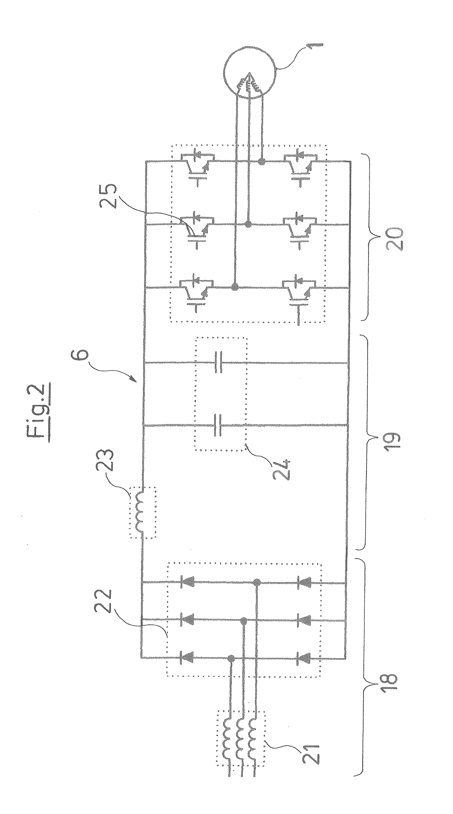
[0016]The previously described design according to the invention moreover permits the heat-producing components of the intermediate circuit as well as of the power circuit to be arranged in an advantageous manner on the same circuit board, which is particularly advantageous, since no cable connections are required between the intermediate circuit and the power circuit, which if they were designed as solder connections, are extensive and bulky and of a hindrance with maintenance and repair purposes, and if they are formed as plug connections, are prone to
fretting corrosion on account of oscillation loading occurring in the housing during operation.

