Turbine assembly and energy transfer method

a technology of turbines and energy transfer methods, applied in the field of turbines, can solve the problems of increasing the cost challenging the current technology of relatively small scale wind turbines, and reducing the efficiency of current or state of the art wind turbines for capturing and transferring energy from turbulent wind sources, etc., to achieve the effect of increasing the efficiency and use of wind

Active Publication Date: 2011-02-03
SCARPELLI TADD M
View PDF32 Cites 7 Cited by
  • Summary
  • Abstract
  • Description
  • Claims
  • Application Information

AI Technical Summary

Benefits of technology

[0026]The blade design and assembly incorporating the same according to the present invention increases efficiency and use of wind from more directions and funnels the wind from previous blade into force of adjacent blade to further rotatabl

Problems solved by technology

The current technology of relatively small scale wind turbines is regionally challenged due to inadequate average wind speeds.
Current or state of the art turbines are relatively inefficient for capturing and transferring energy from turbulent wind sources as compared to the present invention since the inverted tear drop vane or bl

Method used


Image

  • Turbine assembly and energy transfer method
  • Turbine assembly and energy transfer method
  • Turbine assembly and energy transfer method

Examples


Embodiment Construction

)

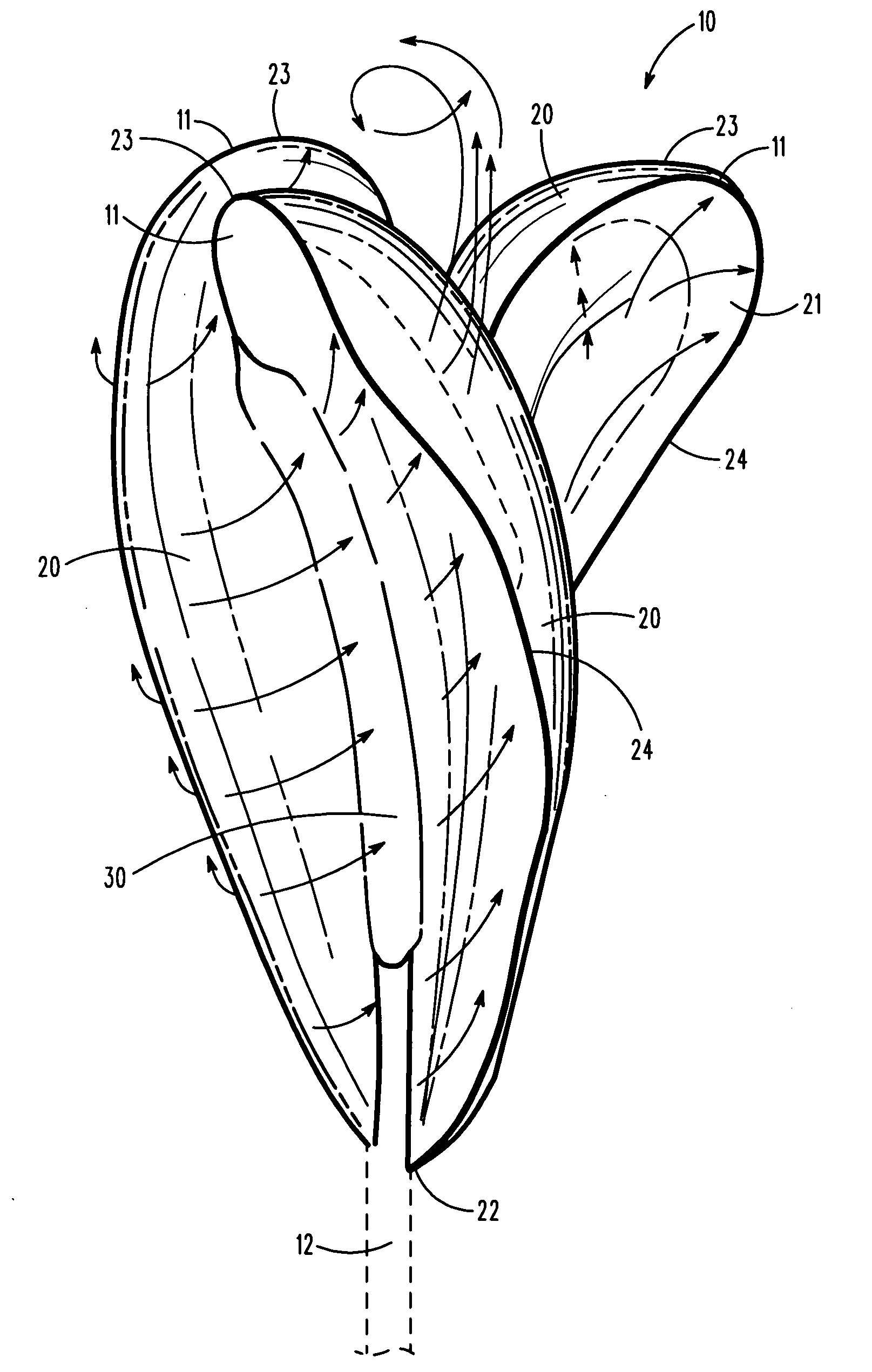
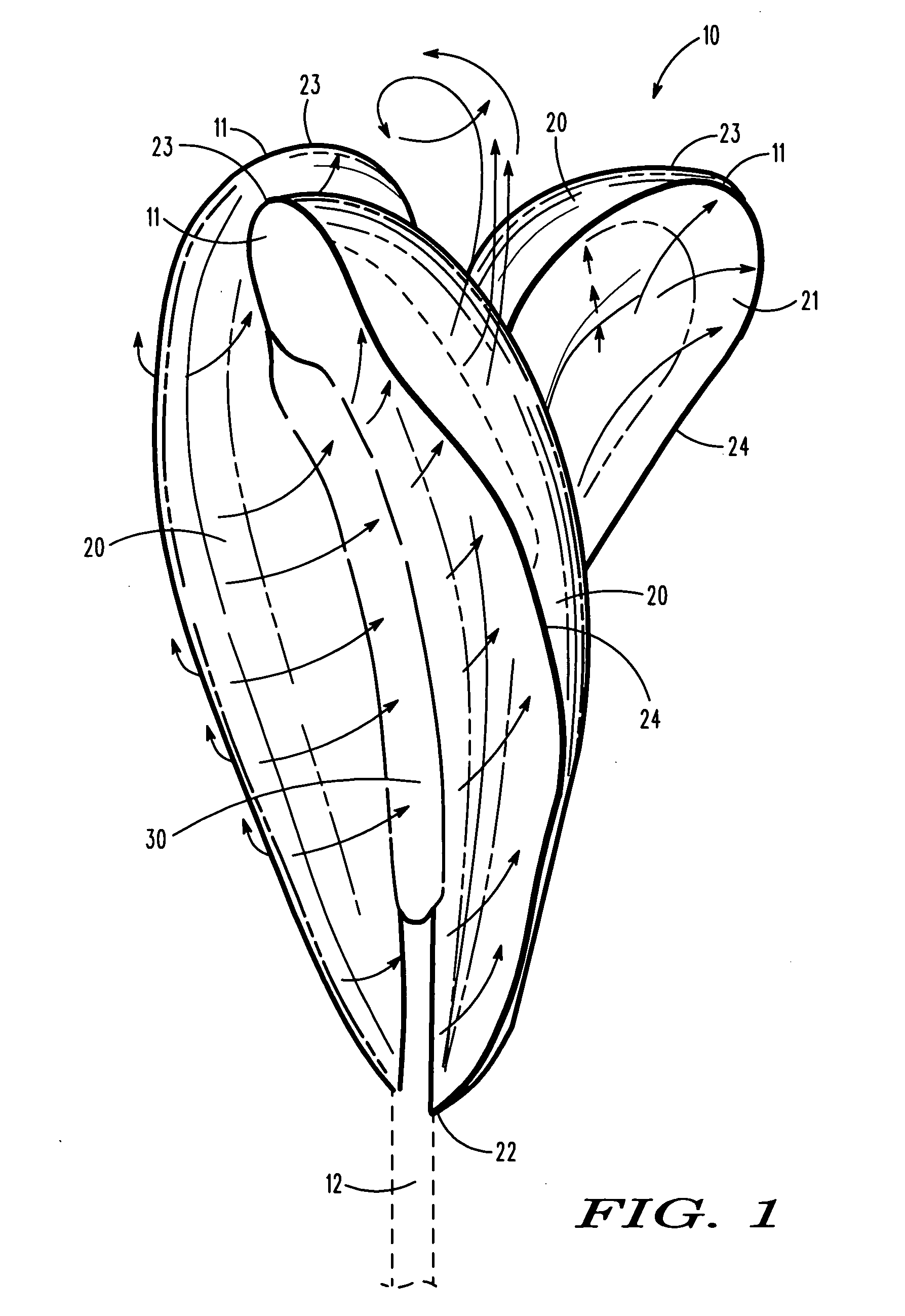
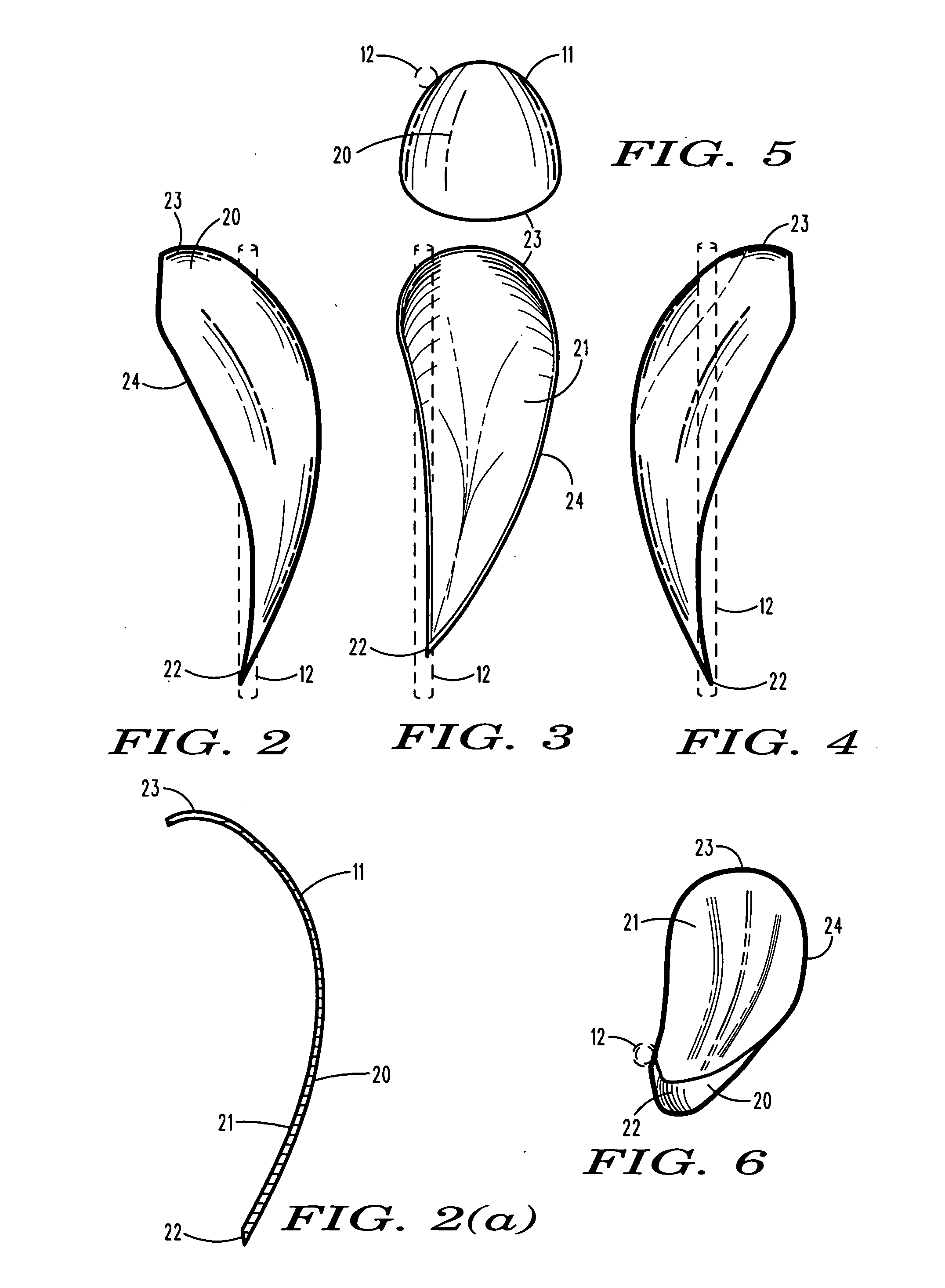
[0041]Referring now to the drawings with more specificity, the preferred embodiment of the present invention is a vertical axis type turbine assembly 10 having a series of vanes 11 or blades substantially equally spaced about the circumference or body of a rotatable spindle or shaft 12 for transferring energy from a fluid current as generally depicted at arrows 100. The rotor or turbine assembly 10 according to the present invention preferably comprises a central shaft 12 and a series of vanes 11 (preferably three), which three vanes 11 or blades are generally spaced 120 degrees from one another as generally depicted in FIGS. 8 and 8(a).

[0042]As generally depicted in the various figures, the shaft 12 is rotatable about an axis of rotation as at 101, and may be outfitted with a generator or certain similar means for generating electricity (not specifically illustrated). The vanes 11 are each attached to the shaft 12 about its circumference and may be described as having an inverted,...


PUM


Abstract

A turbine assembly comprises 2 or more symmetrical vanes or blades attached to a centralized shaft. The assembly may be placed into a fluid current for transferring energy therefrom. Each blade has a scoop with a relatively broader span at the top end and a relatively narrow span at the bottom, which scoop-like vane or blade resembles an inverted tear drop. Eighty-six percent of the potential energy vector is captured within the blade assembly. One end may be connected to a power generation device that will create electrical power when rotated. Certain energy transferring methodology is believed further supported by the vane or blade designed incorporated into the overall turbine assembly.

Description

BACKGROUND OF THE INVENTION[0001]1. Field of the Invention[0002]The present invention generally relates to a turbine for transferring energy from a fluid current. More particularly, the present invention relates to a turbine assembly having uniquely configured inverted tear drop shaped vanes or blades for reacting to a fluid current driven thereagainst and transferring said reaction to a centralized rotatable shaft.[0003]2. Description of Prior Art[0004]U.S. Pat. No. 4,293,274 ('274 Patent), which issued to Gilman, discloses a Vertical Axis Wind Turbine for Generating Usable Energy. The '274 Patent describes a wind turbine for converting wind forces into usable energy having a main shaft rotatably mounted in the axis of rotation for the wind turbine, and a pair of coacting complementary longitudinally extending vane members are connected to each other by a plurality of support and transmission assemblies in the form of articulated members and to the main or driven shaft for driving ...

Claims


Application Information

Patent Timeline
IPC IPC(8): F03D3/00
CPCF03D1/0608F03D3/061Y02E10/74Y02E10/721F05B2210/16Y02E10/72
Inventor SCARPELLI, TADD M.
Owner SCARPELLI TADD M
Why Eureka
Try Eureka